ICCAS2005 June 2-5, KINTEX, Gyeonggi-Do, Korea
1. INTRODUCTION
The design objectives of vehicle suspensions are to improve the ride quality by reducing the vertical vibration from the road and to make the handling performance better by maintaining the traction between the tires and the road. Though passive suspensions with only springs and shock-absorbers are economical in the cost, the energy consumption, and the areas for installation, it is difficult to treat the variable driving environments, using only the fixed design constants. Passive suspensions are very restrictive in the inherent suspension problem, the trade-off between the tide quality and the suspension travel[1]. Since some drawbacks of passive suspensions, active suspensions are used to solve the above problems, having high cost and energy consumption.
The control theories for active suspensions are skyhook control[2] and optimal control[3-5], etc. In this paper, we use LQG(Linear Quadratic Gaussian) controller for the active suspension. It is important to select the appropriate weights in the LQ-objective function, but any clear rules for selection do not exist. So, a designer must depend on the trial and error based on his experiences[6]. From this reason, we replace the designer’s troublesome task with an optimization algorithm, Evolution Strategy(ES) which is a simple algorithm but has an excellent search ability[7]. Using ES, we can find the proper weights and the control gains for selected frequencies which have major effects on the vibrations of the vehicle’s state variables.
The frequencies and proper control gains are used for the neural network training data, as input and output, respectively. During a vehicle running, the trained on-line neural network is activated and provides the proper gains for non-trained frequencies.
2. SUSPENSION MODEL
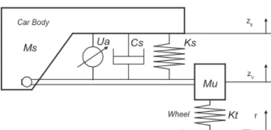
Ms Mu Ks Cs Car Body z s z u r Kt Wheel UaFig. 1 Quarter-car model for Active suspensions.
Fig. 1 shows a quarter car model with the active suspension system composed of a spring, a damper and an active actuator, between sprung mass, Ms and unsprung mass, Mu.
The motion equations from the above quarter car model are represented as follows, a u t u s s u s s u u a u s s u s s s s U r z K z z C z z K z M U z z C z z K z M − − − − + − = + − − − − = ) ( ) ( ) ( ) ( ) ( & & & & & & & & (1)
where Ks is the suspension spring constant, Cs is the
suspension damper constant, Kt is the tire spring constant, and
Ua is the actuator force. zs, zu, and r are the displacements of the sprung mass, the unsprung mass and the disturbance from the road, respectively.
3. DESIGN OF THE CONTROLLER
3.1 LQG
LQG control composes an output feedback controller with an optimal observer and an optimal controller. As the optimal observer, Kalman filter observes the full-state variables from the sensed outputs. The observed full-state variables are used to make the control input with the optimal control gain. LQ-optimal controller has the control objective of minimizing the quadratic objective function for a stabilizable and linear plant. The objective function under this condition is written as following,
{
2 3 2 2 2 1 0 2 ) ( ) ( ( 1lim
E z z z z z r T J s u s u T s T − + + − + =∫
∞ → ρ ρ ρ & & &}
dt U zu a 2 5 2 4 ρ ) ρ + + & (2)The weights {ρ1, ρ2, ρ3, ρ4, ρ5} in the objective function J of Eq. (2) are important elements which determine the poles and eigenvalues of the closed loop system. The state variables,
u
s z
z
x1= − ,
x
2=
z
&
s, x3 =zu−r,x
4=
z
&
uare set up for theabove objective function. We can obtain the actuator force, Ua
= -Kx, using the full-state feedback. By solving the following ARE(Algebraic Ricatti Equation)
0 ) ( ) ( + 1 + + = − +PA PB N R− PB N Q P AT T (3)
where P, the solution of Eq. (3) is a positive semi-definite symmetric matrix, we can take the control gain, K from
A CONTROLLER DESIGN OF ACTIVE SUSPENSION USING
EVOLUTION STRATEGY AND NEURAL NETWORK
Jong-Min Cheon*, Seog-Joo Kim*, Jong-Moo Lee* and Soonman Kwon
**Instrumentation & Control Research Group, Korea Electrotechnology Research Institute, Changwon, Korea (Tel : +82-55-280-1449; Fax : +82-55-280-1476; E-mail: [email protected])
Abstract: In this paper, we design a Linear Quadratic Gaussian controller for the active suspension. We can improve the inherent suspension problem, trade-off between the ride quality and the suspension travel by selecting appropriate weights in the LQ-objective function. Because any definite rules for selecting weights do not exist, we use an optimization-algorithm, Evolution Strategy (ES) to find the proper control gains for selected frequencies, which have major effects on the vibrations of the vehicle’s state variables. The frequencies and proper control gains are used for the neural network data. During a vehicle running, the trained on-line neural network is activated and provides the proper gains for non-trained frequencies. For the full-state feedback control, Kalman filter observes the full states and Fourier transform is used to detect the frequency of the road.
Keywords: Active suspension, LQG controller, Evolution Strategy, Neural Network, Fourier Transform
) (
1 BTP NT
R
K= − + . ‘A’ and ‘B’ are the system matrix and
the input coupling matrix of the given state equation, respectively. Q and R are the state weighting matrix and the control weight matrix in the cost function J, respectively.
LQG has another cost function for observing states. By solving the following FARE(Filter Algebraic Ricatti Equation), 0 1 = Σ Σ − Γ Γ + Σ + Σ − C R C Q A A o T T o T (4)
ΣΣΣΣ, the solution of Eq. (4) gives us the optimal filter gain, L from =Σ −1
o T
R C
L . C, Qo, and Ro are the output matrix, the
disturbance covariance matrix and the sensor noise covariance matrix, respectively.
3.2 Selecting the proper weights through ES
LQ control does not have any clear rules for selecting the proper weights of the optimal control cost function. The designer must depend on the experiential trial and error[6] and so we replace the designer’s troublesome task with ES which is a simple algorithm but has an excellent search ability[7[, in this paper.
Let us show you the method of applying ES to the controller, concretely. LQ optimal control weights are adopted as the competitive individuals, under the driving condition with the road disturbance of a constant frequency and the variables of the fitness function are taken from the system responses of the control gains by optional weights, the individuals in ES. v =[x&1 x1 x2 x3 x4]is used as the variables of the fitness function of Eq. (5).
∑ ∑
= + + = 5 1 2 ) ( 1 1 i a U i s f β α(5) where
∑
∑
= − = m k i i k v k v i 1 2 2 ˆ( ) ) ) (( , viand vˆiare the i-th. Element
of v vector and the maximum permitted limit of v , i respectively. s(.) is the step function and α >> β,
β
≈
1
makes the individual that compels v to stay in the permitted limit with the small Ua get better marks. For example, smaller
1
ˆvwill give the individual with better ride quality and we can obtain the individual reducing the suspension travel, by making ˆv4smaller.
x` = x + N(0, σσσσ) (6) Where N(0, σσσσ) represents a Gaussian random variable with zero-mean and σσσσ standard deviation and the offspring individual, x` is produced from the parent individual, x through the mutation like Eq. (6). The offsprings and the parents will compete each other in the same generation under the same cost function of Eq. (5). In this paper, we use the elitism in which the best individual will be alive certainly and passed to the next generation.
3.3 Training the neural network
Each proper LQ optimal control weight vector of each selected frequency is found by using ES, and each control gain vector can be obtained from each proper weight vector by solving ARE. Some adopted frequencies and the proper control gains of these frequencies are used for the neural
network training data, as input and output, respectively. In this paper, we use a multi-layered neural network of two hidden layers with six nodes and eight nodes, respectively. The back-propagation algorithm was used to train the neural network with one input node and four output nodes.
3.4 Designing the optimal controller
To offer the proper control gain, neural network requires the frequency of the road. Fourier transform is the most frequently used method in the signal processing and analysis[8]. Especially, when we want to know the values of some frequencies included in a signal, this works well.
Fig. 2 The result of frequency reader using Fourier Transform. Fig. 2 shows the result of frequency reader using Fourier transform. First, we get suspension travel data from the LVDT sensor for 1 sec. Using the data, we find the dominant value that means the frequency of the road we are driving on.
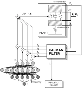
Fig. 3 The block diagram of the whole control system. The block diagram of Fig. 3 shows the whole control system proposed in this paper.
4. SIMULATIONS
Even if we are driving on the road with a constant frequency, the actual road frequency added into the car with varying speed will be not constant. Therefore, we can recognize the fact that the road frequency is related to the car
speed, as well as the road condition. This has made us consider the road frequency as an important control environment.
The skyhook controller which is effective in controlling the car body resonance will be compared with the proposed controller through simulations. We will show the superiority of the proposed controller by analyzing the responses of the ride quality(
z
z&
&
) and the suspension travel(u
s z
z − ) under the various driving conditions
Table.1. Simulation Parameters Car body mass
Ms
290 kg
Wheel mass
Mu
59 kg
Suspension Spring ConstantKs
16,812 N/m
Suspension Damper ConstantCs
1,000 N/(m/sec)
Tire Spring Constant
Kt
190,000 N/m
Fig. 4 The system responses of low freq.(0.4~3 Hz) road input (Upper : Ride quality, Lower : Suspension Travel).
Fig. 5 The system responses of mid. freq.(3~6 Hz) road input (Upper : Ride quality, Lower : Suspension Travel). Fig. 4 and Fig. 5 show the system responses of 0.0245m-magnitude low frequency region(0.4~3Hz) and medium frequency region(3~6 Hz) road input, respectively. In figures, the solid lines and the dotted lines represent the responses of the proposed controller and the skyhook controller, respectively. From the responses in these frequency regions, the ride quality of the proposed controller is superior to the skyhook’s and the responses of the suspension travel are similar, without any restriction in the suspension travel critical
value, ±0.055m[1]. As the frequency increases into the high region, the magnitude of the suspension travel grows and will hit the critical value, ±0.055m. This can result in a big loss in the components of the car, so we have found the proper gains which make the suspension travel reduced at high frequencies.
Fig. 6 The system responses of high freq.(6~11 Hz) road input (Upper : Ride quality, Lower : Suspension Travel). In Fig. 6, we can see the suspension travel did not hit the critical value, ±0.055m but the ride quality was damaged, because of the trade-off between the ride quality and suspension travel.
(a)
(b)
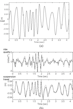
Fig. 7 (a) The road input with various frequencies and magnitudes (b) The system responses of (a) input (Upper : Ride quality, Lower : Suspension Travel). Fig. 7 shows the responses of the road inputs similar to an actual road condition where both the frequency and the road magnitude are varying. When the suspension travel responses of both controllers are similar in ±0.055m, ride quality of the
proposed controller is better than the skyhook controller’s. We may meet the situation of driving through obstacles, like speed bumps and holes. At these occasions, passing the critical value is expected, so we utilize the double skyhook control gains which can reduce the suspension travel effectively[9], on hitting the critical value. In Fig. 8, though the ride quality suffered damaged, the other increase in the suspension travel was obstructed and the components would be protected.
(a)
(b)
Fig. 8 (a) The 0.11m-height speed bump road input (b)The system responses of (a) input (Upper : Ride quality, Lower : Suspension Travel).
4. CONCLUSIONS
In this paper, we have found the proper gains through ES by considering the trade-off between ride quality and suspension travel relevantly and judging the relative importance under a given driving condition based on the road frequency. We have trained the neural network with the found control gains and made sure of the interpolation ability of the neural network which can produce proper outputs from some non-trained input data. Proper control gains from the on-line neural network can make the controller fitted well to any road conditions. When we meet unexpected situations such as speed bumps and holes, we could see the ability to deal with this crisis by using the double skyhook control.
REFERENCES
[1] J. S. Lin and I. Kanellakopoulos, “Nonlinear Design of Active Suspensions,” Journal of IEEE Control Systems, pp. 45-59, 1997.
[2] A. Alleyne and J. K. Hedrick, “Nonlinear Adaptive Control of Active Suspensions,” IEEE Trans. On Control Systems Technology, Vol. 3, No. 1, pp. 94-101, 1995. [3] A. G. Ulsoy, D. Hrovat and T. Tseng, “Stability
Robustness of LQ and LQG Active Suspensions,” Trans. Of ASME J. of Dynamic Systems, Measurement and Control, Vol. 116, pp. 123-131, 1994.
[4] C. Yue, T. Butsuen and J. K. Hedrick, “Alternative Control Laws for Automotive Active Suspensions,” Trans. ASME J. of Dynamic Systems, Measurement and Control, Vol. 111, pp. 286-291, 1989.
[5] L. R. Ray, “Robust Linear-Optimal Control Laws for Active Suspension Systems,” Tans. Of ASME J. of Dynamic Systems, Measurement and Control, Vol. 114, pp. 592-598, 1992.
[6] J. S. Kim, Linear Control System Engineering, Cheongmoongak, Korea, 1997.
[7] Z. Michaelwicz, Genetic Algorithm + Data Structures=Evolution Program. Springer-Verlag, U.S.A., 1994.
[8] G.Y. Park, B.S. Park, J.S. Yoon, D. H. Hong and J. H. Jin, “Development of Fault Monitoring Technique for Agitator Driving System,” Proc. of ICCAS, pp. 1-6, 2002.
[9] S. H. Woo and J. H. Ryu, “A Design of Semi-active suspension system using double sky-hook algorithm,” Proceeding of the Korean Society of Automotive Engineers Autumn Annual Conference, pp. 583-588, 1996.