Structural Design Concept Comparison for GT-MHR and PBMR
Jong-Bum Kim, Yong-Wan Kim, Dong-Ok Kim, Keun-Bae Park, and Jongwha Chang Korea Atomic Energy Research Institute, Dukjin 150, Yuseong, Daejeon, Korea, jbkim@kaeri.re.kr
1. Introduction
The comparison study is performed for the structural design concepts of the GT-MHR(Gas Turbine Modular Helium Reactor) and PBMR(Pebble Bed Modular Reactor). Both are the reference reactors for the NHDD project to develop a high temperature gas reactor to produce hydrogen.
2. Description of GT-MHR
The GT-MHR[1] is composed of the reactor system including reactor internals, the cross vessel system, and the power conversion unit as shown in Fig.1. The design data is shown in Table 1. The hemispherical upper head is bolted to the cylindrical section of the RV and the lower head is welded to the cylindrical section. Though the inner surface of the RV is exposed to the cold gas flow, it is necessary to consider the high temperature structural behavior thus it is designed by ASME III, Subsection NH[2].
Head Insulation Cross Reactor Vessel Refueling Stand Pipe Generator Recuperator Precooler/ Intercooler Head Insulation Cross Reactor Vessel Refueling Stand Pipe Generator Recuperator Precooler/ Intercooler
Figure 1. GT-MHR Module Concept
Most of the reactor internal space is occupied by the prismatic graphite core and reflectors (4.84m in diameter and 8m in height). The core is located inside the metal core support barrel. The cold gas flows upward in the annulus between the RV and the core support barrel. The reactor core is supported on the graphite support columns and the metal core support structure. All the metallic reactor internal structures are made of Alloy 800H which is registered in ASME-NH. The coaxial cross vessel connects the RV to the PCU(Power Conversion Unit). The inside duct transports hot outlet gas from the reactor core to the PCU. The cold inlet gas passes through the annular gap between the hot duct and the cross vessel. The hot duct is thermally insulated from the inside surface. The bellows and the thermal sleeves are applied to absorb the differential thermal expansion between components. The cross vessel is designed per the ASME III, vessel design code instead of piping design.
The PCU is housed in the power conversion vessel. This vessel is made of Mod.9Cr-1Mo steel with overall dimensions of 35m in height, 7.8m in outer diameter, and 0.15m in thickness. The PCU vessel maintains relatively low temperature since it does not contact the hot outlet gas directly. The operating pressure for the vessel is 5~6MPa. The power turbine, intercooler, precooler, recuperator, generator, and high/low pressure compressors are located inside of the PCU vessel. The turbine shroud and the bellows contacting the hot outlet gas are made of Ni-based supper alloys.
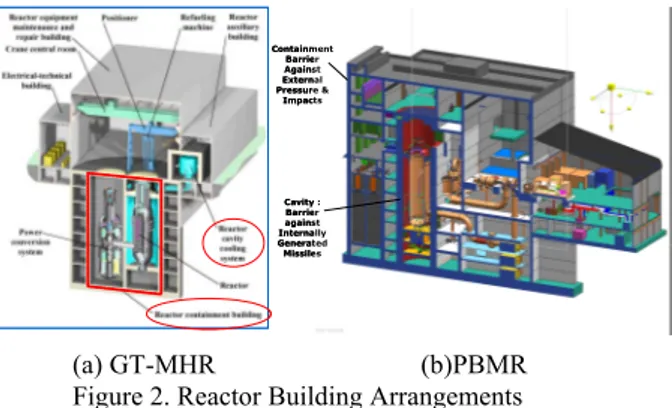
(a) GT-MHR (b)PBMR Figure 2. Reactor Building Arrangements
The RV and the PCU vessel are supported at the same elevation to minimize differential vertical thermal expansion between two vessels, thus minimizing shear and bending moment on the cross vessel.
The RCCS(Reactor Cavity Cooling System), shown in Fig.2(a), serves as passive decay heat removal for the PCU and SCS failures and the RV wall temperature and the concrete cavity temperatures can be maintained within the limits. The containment boundary is red dotted line in Fig.2(a) and it is below grade to increase the defense in depth safety.
3. Description of PBMR
Figure 3 shows the reactor, the power conversion unit, and the piping system of the PBMR[3]. The design data of the RV is shown in Table 1. The torispherical upper head is bolted to the cylindrical section and the lower head is welded to the cylindrical section and incorporates penetrations for the CUD (Core Unloading Discharge) tubes. The low operating temperature of the reactor vessel is obtained by flowing inlet gas through holes inside the side reflectors instead of the annular space between the core barrel and the RV. The RV is designed according to the ASME III, Subsection NB and Code Case N499-2 in the accident condition where the RV temperature reaches 500°C for short duration.
The size of the side reflector is 5.5m in diameter and 0.8m in thickness and the core reflector has 2m diameter. The annular space between two reflectors are filled with the pebble core. The core support barrel,
Containment Barrier Against External Pressure & Impacts Cavity : Barrier against Internally Generated Missiles Containment Barrier Against External Pressure & Impacts Cavity : Barrier against Internally Generated Missiles
Transactions of the Korean Nuclear Society Autumn Meeting Busan, Korea, October 27-28, 2005
made of Type 316 stainless steel according to ASME III Code Case N201-4, supports the core and the reflectors. The single CBSS(Core Barrel Support Structure) located at the bottom of the RV vertically supports the internal structures while allowing the bowing of the core barrel due to the irregular temperature distribution.
Figure 3. PBMR Module Arrangement
The piping system consists of a hot leg piping and two cold leg piping connecting the RV and the PCU. The connecting piping surrounds the hot pipe section transporting the hot outlet gas form the core to the turbine. The structural parts of the piping are subjected to the relatively low temperature since 100°C, 9MPa cold gas flows in the annular space between the hot pipe and the outside connecting pipe.
The PCU is composed of the Power Turbine, HP/LP Compressors, Precooler, Intercooler, Recuperators, and Generators as shown in the Fig.3.
The RCCS, composed of 4 tanks system in the cavity surrounding the reactor vessel, operates in the active mode to circulate cooling water by pumps. When the tank pressure goes high and burst the rupture disks, it discharges generated steams due to boiling into the atmosphere in the passive mode. The containment barrier of PBMR is a single concrete reactor building as shown in Fig.2(b) partially located below grade. The reactor cavity surrounding the reactor vessel provides barrier for the personnel and acts against internally generated missiles.
4. Comparison for Both Reactor Systems
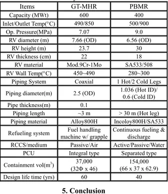
The comparison items for the GT-MHR and PBMR structural design features is presented in Table 1.
PBMR has an economic benefit through the use of carbon steel for the RV due to lowered RV temperature while the GT-MHR uses Mod.9Cr-1Mo. Thus the cost can be reduced. But, GT-MHR achieves economic goals by adopting the integral type PCU and the length of connecting piping is much shorter than that of PBMR. The maintenance of separated type PCU of PBMR is easier than the integral type PCU of GT-MHR due to its structural complexity.
The reactor vessel size of GT-MHR is slightly larger by 8% than the PBMR though the electric capacity is larger by 1.5 times. The design life of the
GT-MHR is 60 years which is requires the extrapolation of design data in the current ASME code while that of PBMR is 40 years. Both reactors utilize the existing materials for low and high temperature components.
The GT-MHR uses the fuel handling machine with grapple and fuel casks while the PBMR applies fueling ports and discharge tubes allowing continuous refueling. Though the PBMR refueling provides convenience, the continuously opened penetrations may be unfavorable for the structural integrity of the RV.
As for the decay heat removal, the GT-MHR employs passive air cooled RCCS while the PBMR employs active/passive water cooled RCCS. Since the GT-MHR containment concept is the medium size concrete building, the containment volume is about 1/4 of that of PBMR of which containment barrier is the whole reactor building. The economics per capacity (MWe) of GT-MHR are better than PBMR for a reactor building construction.
Table 1. Summary of GT-MHR and PBMR Items GT-MHR PBMR
Capacity (MWt) 600 400
Inlet/Outlet Temp(°C) 490/850 500/900 Op. Pressure(MPa) 7.07 9.0
RV diameter (m) 7.66 (OD) 6.56 (OD) RV height (m) 23.7 30 RV thickness (cm) 22 18
RV material Mod.9Cr-1Mo SA533/508
RV Wall Temp(°C) 450~490 280~300 Piping System Coaxial 1 Hot/2 Cold Legs Piping diameter(m) 2.5 (OD) 1.036 (Hot ID)/ 0.6 (Cold ID)
Pipe thickness(m) 0.1
Piping length ~3 m > 30 m (Hot leg) Piping material Alloy800H Incoloy800H/SA533 Refueling system machine w/ grapple Fuel handling Continuous fueling & discharge
RCCS/medium Passive/Air Active/Passive/Water PCU Integral type Separated type Containment vol(m3) 37,000
(32Φ x 46) (66 x 37 x 62.9) 154,000 Design life time (yrs) 60 40
5. Conclusion
The structural design concepts for GT-MHR and PBMR were compared. Since each concept has merit and demerit, it is premature to judge the relative merits and the detailed analysis is necessary.
Acknowledgement
This study was supported by the Korean Ministry of Science & Technology through its National Nuclear Technology Program.
REFERENCES
[1]GA, GT-MHR Concept Design Description Report, 1996. [2] ASME Section III, Subsection NH, Class 1 Components in Elevated Temperature Service, 2004
[3]P.J.Venter, "PBMR Reactor Design and Development', S02-2, SMiRT 18, Beijing, China, August, 2005