Research Article
An Efficient Local Repair-Based Multi-Constrained Routing for
Congestion Control in Wireless Mesh Networks
Byoungheon Shin
and Dongman Lee
School of Computing, KAIST, Daehak-ro 291, Yuseong-gu, Daejeon 34141, Republic of Korea Correspondence should be addressed to Byoungheon Shin; [email protected]
Received 7 September 2018; Accepted 31 October 2018; Published 14 November 2018 Academic Editor: Junaid Qadir
Copyright © 2018 Byoungheon Shin and Dongman Lee. This is an open access article distributed under the Creative Commons Attribution License, which permits unrestricted use, distribution, and reproduction in any medium, provided the original work is properly cited.
Multi-constrained routing is a key driver to support quality-of-service (QoS) for real-time multimedia applications in wireless mesh networks (WMNs). Due to the difficulty of applying strict admission control into a public WMN, it is inevitable to accommodate multiple application flows with different QoS requirements exceeding the capacity of a certain link shared by multiple flows. However, existing multi-constrained routing protocols under such an environment find the QoS degradation based on end-to-end path quality probing and trigger flooding-based route discovery from a scratch for resolving the QoS degradation, which incurs a longer recovery time and much routing overhead. In this paper, we propose a novel multi-constrained routing protocol for WMNs that finds problematic links that may affect QoS degradation to end-to-end paths and replaces them with a detour path using a local repair principle. We model congestion threshold estimation for finding problematic links and design algorithms for quickly finding detour paths and selecting an optimal path by minimizing the negative effect on existing flows nearby the detour path. Simulation results show that the proposed routing protocol achieves up to 19.6% more goodput of live video streaming applications with up to 33% reduced routing overhead compared with an existing work.
1. Introduction
A wireless mesh network (WMN) is a promising network infrastructure for mobile devices in a public space which extends connectivity with self-configuration between dis-tributed mesh routers [1]. As the use of real-time multimedia applications in mobile devices is increasing, guaranteeing the quality-of-service (QoS) becomes important, which includes available bandwidth, end-to-end delay, jitter, and packet loss rate. A multi-constrained routing protocol [2–4] has attracted researchers’ attention since it is able to discover a routing path considering multiple link quality metrics at the same time. It is designed for providing an application with feasible routing paths which satisfy multiple constraints based on link quality measurement.
For guaranteeing QoS, many multi-constrained routing protocols assume admission control in a network which allocates a certain amount of network resources to a specific flow and blocks an additional flow request if the request exceeds available network capacity. However, applying such
strict admission control in a public WMN is undesirable
due to network resources underutilization. Because the QoS requirement of an application usually can be specified based on its peak usage, guaranteeing QoS for the application can be overprovisioning QoS, which leads to inefficient network resource utilization [5–7]. Moreover, due to the mobility of mesh clients transiting multiple mesh routers, the amount of traffic to be guaranteed with a specific QoS requirement will vary over time. This opens up a new challenge to existing multi-constrained routing protocols for public WMNs: If admission control gets relaxed, that is, links are allowed to accommodate traffic flows exceeding their available capacity, there is a need to deal with congestions and the QoS degradation of application flows. However, existing multi-constrained routing protocols wait until when a target flow faces unacceptable QoS degradation due to congestions and rediscover a new routing path from a scratch. It leads to severe goodput degradation in the viewpoint of an application layer. A fast and lightweight solution for resolving the QoS degradation of a multihop routing path is necessary.
Volume 2018, Article ID 2893494, 17 pages https://doi.org/10.1155/2018/2893494
In this paper, we propose a new multi-constrained routing protocol in WMNs that (1) finds links that would hamper a target application’s end-to-end QoS by estimating the congestion threshold of each link and (2) replaces a link(s) performing lower than the required QoS with a detour path to recover the end-to-end QoS requirement exploiting the information of neighbor mesh routers. For additive and multiplicative QoS metrics, the congestion threshold of each link is defined as the tolerance level of how much the quality of each link can be deteriorated while the end-to-end path quality still satisfies the applications’ QoS requirement. If a link exceeds its congestion threshold, the source node of a link finds candidates among its neighbor nodes which have connectivity to the sink node of the link. For each candidate neighbor node, the source node checks if a detour path via the candidate neighbor node is feasible, that is, the quality of the detour path is below the congestion threshold. In order to select one of multiple detour paths satisfying the congestion threshold, we define an optimization function that estimates the negative effect on existing flows nearby the detour path. Using the optimization function, the best path with the smallest negative effect on nearby existing flows is selected for local repair.
The simulation results show that the proposed local repair scheme outperforms the route discovery approach in exist-ing multi-constrained routexist-ing protocols under congested environments in terms of the goodput of a real-time video streaming application, route maintenance time, and routing overhead. We achieve up to 19.6% higher goodput and up to 33% smaller routing overhead. The total number of flooding-based route discovery triggered for route recovery is also reduced up to 40.8% in our proposed scheme.
The rest of this paper is organized as follows. Section 2 illustrates a motivating scenario where a routing path gets degraded due to congestion and recovered using an existing multi-constrained route discovery scheme. Section 3 explains the system model of multi-constrained routing and the estimation of QoS degradation in a distributed manner for applying local repair. In Section 4, we explain the proposed scheme in the viewpoint of routing operations. In Section 5, we show simulation results of the proposed scheme compared with an existing multi-constrained routing protocol. We explain related works in Section 6, and we conclude in Section 7.
2. A Motivating Scenario
We illustrate a motivating scenario for proving the need of fast and lightweight route maintenance for multi-constrained routing protocols. In WMNs, many mobile devices join the network through one of the closest mesh routers and run a variety of applications with different QoS requirements. Assume that there is a WMN where each link between arbi-trary mesh routers has bandwidth of 5 Mbps and latency of 2 ms. Consider two different types of applications: a live video streaming application and a remote desktop application. The live video streaming application has stringent bandwidth and delay requirements (3 Mbps, 20ms) for clear and smooth video playback, and the remote desktop application also
6 5 3 11 2 9 12 10 4 8 13 7 1
Live video streaming Remote desktop Best effort
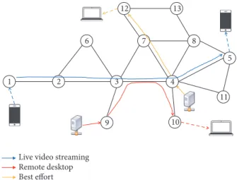
Figure 1: An example topology of a wireless mesh network (mesh routers) with multiple simultaneous application flows.
demands a certain level of bandwidth (2.8 Mbps) for getting updates of screen refreshes in a remote machine. Assume that there is best effort traffic in the network which does not have any specific QoS requirement but consumes available bandwidth for delivering packets as many as possible.
As shown in Figure 1, two smartphones are connected with node (mesh router) 1 and node 5, respectively, and a routing path (a red line) from node 1 to node 5 is established for serving the traffic of a live video streaming application. In addition, a laptop connected with node 10 runs a remote desktop application and receives data stream from a remote machine connected with node 9. At first, a routing path for the remote desktop application is established through nodes 9-3-4-10, and the remote desktop flow consumes 1.76 Mbps of bandwidth although its bandwidth requirement is 2.8 Mbps. After that, a live video streaming application starts and con-sumes bandwidth of 3 Mbps. Since the available bandwidth of the link between node 3 and node 4 is 3.24 Mbps, the link can accommodate the live video streaming flow. Then a routing path for the live video streaming application is established through nodes 1-2-3-4-5 as the shortest feasible path (i.e., the smallest end-to-end delay). However, the remote desktop application consumes more bandwidth due to user activity and frequent screen updates, and the aggregate bandwidth consumption of both applications exceeds the capacity of the common link from node 3 to node 4. Then congestion occurs at the link 3-4, and the transmission queue size continuously increases at node 3. This makes both applications contend at the link 3-4 using less bandwidth than requested.
If the routing protocol does not monitor this quality degradation, the routing paths for both applications will stay as originally discovered because this situation is not a link break. In order to solve this quality degradation, one or more routing paths need to be reconfigured. One possible option is to perform route discovery again for problematic flows treating this situation the same as link break. The route discovery for QoS-degraded flows could cause critical per-formance degradation since it stops all associated application flows on a routing path, and the applications experience
G o o d p u t (k b ps) 0 1000 2000 3000 4000 5000 1 11 21 31 41 51 61 71 81 91 Time (s)
Live video streaming Remote desktop
(a)
Live video streaming Remote desktop 0 500 1000 1500 2000 2500 3000 3500 4000 4500 5000 1 11 21 31 41 51 61 71 81 91 G o o d p u t (k b ps) Time (s) (b)
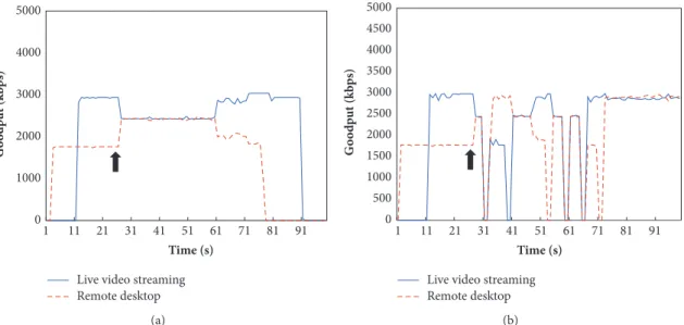
Figure 2: Goodput of live video streaming and remote desktop applications over time with the existence of background best effort traffic. The side (a) is the case of leaving both routing paths, and the side (b) is the case of running route discovery for the live video streaming flow. QoS degradation due to congestion occurs at 25s.
disconnection until a new route is established. Figure 2 shows an effect of route discovery as a result of simulating our motivating scenario in the ns-3 network simulator. The result (a) shows a case that the underlying routing protocol does not respond to QoS degradation, and the result (b) is about the case that route discovery is performed for both application flows. If the network leaves QoS degradation, then the problem lasts until one of the contending flows stops. If routes are rediscovered for QoS degradation, the applications are completely disconnected until a new route is established for each one. For route discovery, we set a route discovery timeout for accepting multiple route reply messages as one second. In the right result, both flows trigger route discovery at the same time and their established routing path experience congestion again, which triggers another route discovery. That is, new routing paths for both applications would discover a routing path avoiding the link 3-4, and both of them establish new routes passing through the partial path 3-7-4. Thus, performing route discovery for every QoS-degraded flow is not desirable for an application layer in terms of user experience (UX). Although we can reduce the route discovery timeout to millisecond levels, the application layer disconnection is unavoidable. This motivates studying a fast and local route reconfiguration scheme for quickly resolving QoS degradation and preserving application goodput.
3. System Model
This section describes models for basic multi-constrained routing and congestion threshold estimation for detecting QoS degradation in a distributed manner using common notations.
3.1. Basic Multi-Constrained Routing Model. Our model is
based on existing multi-constrained path algorithms [3, 8, 9]. We model the network of mesh routers as a directed graph
𝐺 = (𝑉, 𝐸), where 𝑉 is the set of nodes and 𝐸 is the set
of links (𝑖, 𝑗) between two nodes 𝑖 and 𝑗. For total 𝐾 link
quality metrics (equals the number of constraints), there is
a link quality for the 𝑘th metric 𝑤𝑘(𝑖, 𝑗), 𝑘 = 1, 2, . . . , 𝐾,
between two nodes𝑖 and 𝑗. A path 𝑝 = ((𝑠, 𝑖), (𝑖, 𝑗), . . . , (𝑟, 𝑑))
is a sequence of links connecting nodes from a source
node 𝑠 to a destination node 𝑑. A path quality 𝑤(𝑝) is a
set of path quality values for the 𝑘th metric 𝑤𝑘(𝑝), where
𝑤𝑘(𝑝) is the aggregation of all associated links quality values
for the 𝑘th metric. The aggregation function is separately
defined for each metric type. A metric type 𝑚𝑘 for a link
quality metric 𝑘 has one of the following values: additive,
multiplicative, concave, and maximum representative. For an additive metric type, a path quality should be the sum of all individual link quality values. The link quality aggregation
function for metric𝑘 is defined as
𝑤𝑘(𝑝) = ∑
(𝑖,𝑗)∈𝑝
𝑤𝑘(𝑖, 𝑗) , 𝑤𝑘≥ 0 (1)
For a multiplicative metric type, the aggregation function becomes a product of all individual link quality values like
𝑤𝑘(𝑝) = ∏
(𝑖,𝑗)∈𝑝
𝑤𝑘(𝑖, 𝑗) (2)
For a concave metric type such as bandwidth, a bottleneck link is directly concerned to its end-to-end path quality. Thus, the aggregation function for a concave metric type is a minimum of all individual link quality values like
𝑤𝑘(𝑝) = min {(𝑖, 𝑗) ∈ 𝑝 | 𝑤𝑘(𝑖, 𝑗)} (3)
In contrast to the concave metric, a maximum representative metric type requires a maximum value. The aggregation function is
𝑤𝑘(𝑝) = max {(𝑖, 𝑗) ∈ 𝑝 | 𝑤𝑘(𝑖, 𝑗)} (4)
A constraint for the𝑘th metric is defined as 𝑐𝑘 ≥ 0, and
requirement using a constraint set𝐶 = {𝑐𝑘 | 1 ≤ 𝑘 ≤ 𝐾}. Then the goal of a multi-constrained routing protocol
is to find a feasible routing path that satisfies all𝑐𝑘 ∈ 𝐶. In
order to check whether the routing path𝑝 is feasible or not
according to constraints𝑐𝑘 ∈ 𝐶, an evaluation function of 𝑝
and𝑐𝑘is necessary. Note that the evaluation criterion depends
on the metric type 𝑚𝑘. If𝑚𝑘 is additive, the path quality
that is the addition of all individual link’s quality should not
exceed the constraint. If𝑚𝑘 is concave, the minimum value
of all link quality values should be bigger than the constraint. For example, a delay requirement given by an application should be the upper limit of the end-to-end delay of a path (smaller than the requirement). On the other hand, a band-width requirement becomes a lower bound to be achieved (greater than the requirement). Using the Iverson bracket [10] for representing boolean values, we define the evaluation function as
𝑠𝑘(𝑝, 𝑐𝑘)
={{ {
[𝑤𝑘(𝑝) ≤ 𝑐𝑘] , if 𝑚𝑘is additive or multiplicative
[𝑤𝑘(𝑝) ≥ 𝑐𝑘] , if 𝑚𝑘is concave or max representative
(5)
where the result becomes either 0 or 1. If the value is 1, then
the path𝑝 is called feasible for the constraint 𝑐𝑘. If the result
of𝑠𝑘is 1 for all𝑘, then the path is feasible for all constraints.
Therefore, we define a path evaluation function𝑠 as
𝑠 (𝑝, 𝐶) = [∑𝐾
𝑘=1
𝑠𝑘(𝑝, 𝑐𝑘) = 𝐾] (6)
where𝑐𝑘 ∈ 𝐶.
Using the path evaluation function, we can obtain a set
of candidate paths𝑃𝐶such that∀𝑝 ∈ 𝑃𝐶, 𝑠(𝑝, 𝐶) = 1. Then
at least one or more paths should be selected for delivering
application traffic. In other words,𝑃𝐶needs to be sorted. For
this, we define an optimization function𝑓𝑜(𝑝). As analyzed
in [11], the optimization function may have various forms according to major application demands. In this paper, we use concave metrics, especially an available bandwidth, to define the optimization function. Since there can be multiple concave metrics, we exploit a normalized weighted sum. A path with the largest quality of concave metrics is considered optimal, which is described as
𝑓𝑜(𝑝) = ∑
𝑘
𝛼𝑘𝑤𝑘(𝑝)
max{𝑤𝑘(𝑝) | 𝑝 ∈ 𝑃𝐶} (7)
for all concave type constraints 𝑘, where 𝛼𝑘 is a weighting
factor of each concave type constraint.
Though many algorithmic approaches [2, 3, 12, 13] for finding multi-constrained paths focus on additive metrics, we also consider multiplicative, concave, and maximum repre-sentative metric types altogether because an application’s QoS requirement is represented with an arbitrary set of various QoS metrics. In the real world, bandwidth, one of the famous concave metrics, is widely used as a routing metric. Thus, we clearly express all metric types to be utilized for a multi-constrained routing protocol in practice. Moreover, the goal of this paper is to design and evaluate the effect of local repair
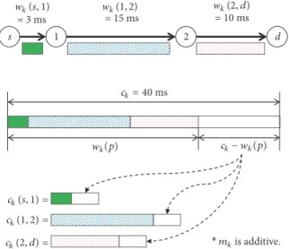
2 1 d s wk(s, 1) w w k(1, 2) wk(2, d) = 3 ms = 15 ms = 10 ms ck= 40 ms ck(s, 1) = ck(1, 2) = ck(2, d) = k(p) wk mkis additive. ck− (p) ∗
Figure 3: An example of deriving congestion threshold from an end-to-end constraint and path quality in case of an additive metric type.
by implementing a multi-constrained routing protocol with commonly used link quality metrics including bandwidth, end-to-end delay, delay jitter, and packet loss rate.
3.2. Congestion Threshold Estimation for Detecting QoS Degra-dation. We derive congestion threshold from a constraint,
end-to-end path quality, and a path length for the𝑘th metric.
The congestion threshold can only be calculated for a feasible
path where𝑠𝑘(𝑝, 𝑐𝑘) = 1. Then it is expected that there exists a
remaining amount of the corresponding network resource for
the metric𝑚𝑘. Such remaining amount of network resource
can be used as a room for the current path to be deteriorated without losing feasibility. Now we can allow each link on the path to consume some of the remaining resource. We divide the remaining amount by the path length in order for each link to fairly consume the additional amount of network resource. The way of dividing the remaining amount
of network resource depends on the metric type 𝑚𝑘. We
define𝑐𝑘(𝑖, 𝑗) as the congestion threshold of the 𝑘th metric
for a link(𝑖, 𝑗).
If 𝑚𝑘 is additive, the remaining amount of network
resource is calculated by simply subtracting the constraint
with the end-to-end path quality,𝑐𝑘−𝑤𝑘(𝑝). By arithmetically
dividing the remaining amount by the path length, we get the congestion threshold for an additive metric as
𝑐𝑘(𝑖, 𝑗) = 𝑤𝑘(𝑖, 𝑗) +𝑐𝑘− 𝑤𝑙𝑘(𝑝)
𝑝 , 𝑚𝑘
is additive (8)
Figure 3 shows how the congestion threshold of an addi-tive metric type is calculated for each link on a path from the
source𝑠 to the destination 𝑑. The colored areas indicate the
currently measured quality of each link, and the white area is
the remaining amount of network resource for the𝑘th
con-straint. Because the quality of each link continuously changes over time, the congestion threshold is estimated periodically. For a multiplicative metric, the way of obtaining the remaining amount of network resource is different from
additive metrics because individual link quality values are accumulated by multiplication. We need to obtain how much additional value could be multiplied to the current path quality while feasibility is still maintained. So we divide the
constraint𝑐𝑘by the current path quality𝑤𝑘(𝑝). In order to
derive the congestion threshold from the remaining amount of resource, we use square root of the path length. Thus, the resulting congestion threshold for a multiplicative metric is
𝑐𝑘(𝑖, 𝑗) = 𝑤𝑘(𝑖, 𝑗) × 𝑙𝑝√𝑤𝑐𝑘
𝑘(𝑝),
𝑚𝑘 is multiplicative
(9)
For concave or maximum representative metrics, only the bottleneck or the maximum link quality of all links is meaningful. Thus, the congestion threshold must be the same as the constraint. The congestion threshold for both concave and maximum representative metrics is
𝑐𝑘(𝑖, 𝑗) = 𝑐𝑘,
𝑚𝑘 is concave or maximum representative (10)
As already described in (5) for a path𝑝, we can also define
an evaluation function of a link with the congestion threshold as follows:
𝑠𝑘((𝑖, 𝑗) , 𝑐𝑘(𝑖, 𝑗)) ={{
{
[𝑤𝑘(𝑖, 𝑗) ≤ 𝑐𝑘(𝑖, 𝑗)] , if 𝑚𝑘 is additive or multiplicative
[𝑤𝑘(𝑖, 𝑗) ≥ 𝑐𝑘(𝑖, 𝑗)] , if 𝑚𝑘 is concave or max representative (11)
Let𝐶𝑖,𝑗 = {𝑐𝑘(𝑖, 𝑗) | 1 ≤ 𝑘 ≤ 𝐾} be a set of congestion
thresholds for all𝑘 metrics. Then, following (6) for a path 𝑝,
we define an evaluation function for a link(𝑖, 𝑗) with a set of
congestion thresholds𝐶𝑖,𝑗as follows:
𝑠 ((𝑖, 𝑗) , 𝐶𝑖,𝑗) = [∑𝐾
𝑘=1
𝑠𝑘((𝑖, 𝑗) , 𝑐𝑘(𝑖, 𝑗)) = 𝐾] (12)
If𝑠((𝑖, 𝑗), 𝐶𝑖,𝑗) is one, then the link (𝑖, 𝑗) is considered as
satisfying the application’s QoS requirement.
4. A Local Repair-Based Multi-Constrained
Routing Protocol
This section explains how the proposed protocol dynamically and efficiently preserves the QoS requirement of a given end-to-end path based on local repair in the presence of QoS degradation due to network congestions. For this, the proposed protocol defines new modules and operations for local repair while it adopts the distributed source-based routing concept and the flooding-based route discovery pro-cedure commonly used in existing multi-constrained routing protocols [14, 15].
4.1. Key Design Considerations. We consider the following
key design issues for the proposed protocol:
(1) Estimating end-to-end path quality degradation
from local network congestion in a distributed manner with a minimum cost: a WMN is a distributed environment
where each mesh router measures multiple link quality metrics with neighbor nodes. It is very costly for a mesh router to keep track of the multiple link quality metrics of arbitrary nodes further than one-hop in which the search space exponentially increases by the number of nodes and the number of links. To monitor the changes in multiple quality metrics of a path, the source has to send a probing message to the destination so that the probing message could accumulate
multiple quality metrics traversing every intermediate node on the path. QoS degradation can be detected by monitoring such end-to-end path quality, but it requires time for the probing message to travel along the path. Since each link can be monitored by each intermediate node (i.e., the receiver side of the link) without creating additional probing messages for aggregating path quality, estimating QoS degradation based on the network congestion of each link is desirable for fast degradation detection and low monitoring cost.
(2) Efficiently finding alternative intermediate paths
for local congestion repair: as the network congestion in a
certain link(s) is identified as a potential cause to end-to-end path quality degradation, a next job is to find alternative detour paths around the link. For this, the source node of the problematic link has to know the connectivity information of its neighbor (i.e., the neighbors of a neighbor) to find nodes which has a direct connection to both sides of the link. Then, in order for these neighbors to determine whether a detour path via each of them can assume the congestion that occurred at the link, they should get informed of the congestion threshold of the link.
(3) Selecting a detour path incurring a minimum
negative effect on existing flows: if one of the alternative path
candidates is randomly chosen without considering the flows that already use the path, it could cause a serious side effect: that is, such existing flows could experience network conges-tion due to an addiconges-tional allocaconges-tion of network resources for the alternative path, which in turn results in another local repair on nearby nodes and further. Therefore, we should minimize such consecutive occurrences of congestion, which we call the congestion domino effect. For this, the resource usage of existing flows around each alternative path candidate should be taken into account. However, it is not efficient to catch up with all different types of constraints for all neighbors. Among multiple constraints, we need to focus on the resource usage of the most important constraint which reduces the search space most. Concave or maximum repre-sentative metric types have the characteristic of pruning the
Flow ID Src Sport Dst Dport Constraints Congestion Thresholds Dst Flag Flow ID Next Hop
Addr LinkQuality Neighbors BandwidthsNeighbor Flow SeqNo Flow Table Route Table Neighbor Table Hop Count : a list structure LR Count ∗ ∗ ∗ ∗ ∗ ∗
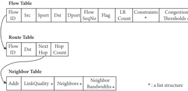
Figure 4: The basic structure of a flow table, a route table, and a neighbor table in the proposed routing protocol.
search space, and one of the representative concave metrics is available bandwidth. Thus, the bandwidth occupation of existing flows nearby the detour path candidate should be considered for estimating the congestion domino effect.
4.2. Congestion Threshold Estimation and Link Evaluation.
The congestion threshold of a link for a specific flow is estimated from the measurement of the link and the path associated with the flow. In order to maintain the information of a flow, the flow’s associated routing path, and real-time link quality, each node has three table structures: a flow table, a route table, and a neighbor table. The flow table is used for storing the information of a flow which passes through the node. The route table is an extension of a commodity route table in commodity operating systems in order to provide a route for a specific flow. The neighbor table maintains necessary information for multi-constrained routing and local repair including multiple link quality metrics and con-nectivity information of neighbors. The column structures of the tables are described in Figure 4. A flow table maintains necessary information for supporting QoS constraints of an individual application including the flow information (a flow ID, a source address, a source port number, a destination address, a destination port number, and a flow sequence number), a flag for checking QoS degradation, a LR Count for checking the number of local repairs performed, application-driven constraints, and the congestion threshold values for the associated link. A route table maintains route entries based on a flow as an identifier so that a next-hop can be found using a flow ID. There are also default routes which provide all background traffic without specifying flow information. A neighbor table manages multiple link quality metrics for all neighbor nodes which are directly connected with a single-hop link. Based on piggybacked Hello messages, it also maintains the list of neighbors of each neighbor and the average available bandwidth of them, thereby catching up the traffic status of the two-hop scope.
In this paper, we use four different link quality metrics: available bandwidth (concave), delay (additive), delay jitter (additive), and packet loss rate (multiplicative). Available bandwidth can be estimated in various ways such as exchang-ing probexchang-ing packets or calculatexchang-ing idle times of the net-work interface [16]. Because iperf, a well-known bandwidth
benchmarking tool, generates many packets, it is not desir-able to continuously run it due to network overhead. The available bandwidth estimation scheme based on idle times is suitable for WMNs because we can exploit current modu-lation scheme and channel idle ratio for estimating available bandwidth. For delay measurement, two nodes on a link measure a round trip time (RTT) using probing messages and divide by two to obtain the one-way link delay. Delay jitter is calculated by the difference of consecutive arrivals of probing messages used for measuring the RTT [17]. To obtain packet loss rate, we count the number of successfully received probing messages for a certain duration and get the portion of the successful receptions over the total expected number of receptions, which is proposed in the Expected Transmission Time (ETX) [18]. We use Hello messages for the probing message for the packet loss rate.
As illustrated in (8), (9), and (10), the congestion thresh-old at each link depends on the quality of both an individual link and an end-to-end path. Link quality can be measured at any time in each intermediate node, but the end-to-end path quality should be shared through message passing along the path. For this, we define two types of probing messages:
PathProbe and PathQualityReport.
The role of a PathProbe message is to measure the end-to-end path quality by traversing individual links of the path. A source node periodically creates a PathProbe and unicasts it to the next-hop of the path. The period of sending PathProbe messages is set to one second. A PathProbe contains flow information, a flow sequence number, a QoS requirement length, a QoS requirement field, a path quality length, and a path quality field. The path quality field is used for accumulating multiple link quality metrics over the path. In order to reduce the size of control messages, the QoS requirement field is by default empty (i.e., QoS requirement length is zero) unless the application changes its requirement. If the QoS requirement length in the PathProbe is zero, each intermediate node loads the existing QoS requirement from its flow table using the flow information written in PathProbe. Otherwise, each intermediate node updates its flow table with the new QoS requirement, in other words, a set of updated constraints.
A destination node receiving the PathProbe replies back to the source with a PathQualityReport through the reverse path of the flow. The role of the PathQualityReport is to share the measured end-to-end path quality with source and inter-mediate nodes on the path. A PathQualityReport contains a flow, a flow sequence number, a path quality length, and a path quality field. The destination copies flow information, a flow sequence number, and the path quality information from the received PathProbe into a new PathQualityReport. Intermediate nodes receiving the PathQualityReport updates its flow table with the path quality field in the message. Using the new path quality, the intermediate node calculates the congestion threshold of a link between itself and its predecessor. Until next PathQualityReport reception, the intermediate node uses the congestion threshold for evalu-ating its associated link.
Using the congestion threshold, each intermediate node checks whether its corresponding link satisfies the congestion
threshold, which is associated with a link evaluation function in (11). As we measure link quality on the receiver side (i.e., successor) of the link, the link evaluation is also performed at the receiver side. Note that the period evaluating each link is independent of that sending PathProbe. It depends on the updating cycle of link quality metrics such as available bandwidth or delay. The procedure updating the congestion threshold for each link is done by the round trip of PathProbe and PathQualityReport messages between a source and a destination. On the other hand, the procedure evaluating each link’s QoS degradation runs in an independent thread without being affected during exchanging PathProbe and
PathQualityReport messages. The link evaluation cycle based
on the congestion threshold can be adjusted to the speed at which each intermediate node measures the link quality. The intermediate node may actively reduce the link evaluation cycle as needed to predict the QoS degradation or, conversely, increase the evaluation period to reduce the computation overhead of each intermediate node. Since both a Hello messaging interval and a delay measurement cycle are one second in our scheme, we also set the link evaluation cycle as one second by default.
Due to the mobility of mesh clients which also act as data sources, application traffic in the network may change over time. When a mesh router serves an application flow generated by a specific mesh client, then the flow can be disconnected and restarted at another mesh router due to the client’s movement. Then, this mesh router may experience congestion if there are other existing flows. On the other hand, the previous mesh router may be mitigated by the mesh client. In order to handle such dynamic situations, we define the QoS degradation threshold, which indicates the consecutive number of QoS degradation occurring at the same flow. For this, we run the evaluation function periodically per unit time. In this paper, we set the QoS degradation threshold to three.
4.3. Local Repair based on Congestion Domino Effect. If any
intermediate node finds its link evaluation function yields a false result, the link is treated as QoS-degraded. Then the node starts investigating whether any of its neighbor nodes can provide a detour path for the QoS-degraded flow. The detour path has the following conditions: (1) a new intermediate node in the middle of the detour path must be directly connected to both the predecessor and successor of the QoS-degraded link; (2) the detour path must satisfy the congestion threshold of the QoS-degraded link, which is feasible in other words. The procedure of searching a set of detour paths is described in Algorithm 1.
Based on connectivity information, an intermediate node of a certain link recognizing QoS degradation searches a set of common neighbors of both the source and the sink of the link. One common neighbor has a two-hop detour path starting from the source of the QoS-degraded link and ending at the sink passing through the common neighbor node. Since the intermediate node (the source of the degraded link) already knows the quality of a link between itself and the common neighbor, it writes the link quality to a new control message called Flow Accept Request (FAREQ). The role of a
s i j d 1 2 3 FAREQ.TTL = 2 s i j d 1 2 3 feasible infeasible FAREQ.TTL = 1
Figure 5: The difference in a set of detour paths for a QoS-degraded link between nodes𝑖 and 𝑗 with different local repair scopes using the TTL value in the FAREQ.
FAREQ is to ask the common neighbor to check whether
the detour path including itself can accept a new flow. The
FAREQ contains flow information, a flow sequence number, a
time-to-live (TTL) value, congestion thresholds of all metrics, and path quality. The common neighbor node receiving the
FAREQ accumulates the quality of a link between itself and
the sink of the original link to the path quality field and evaluates it with the congestion threshold. If the detour path is determined feasible by the link evaluation function, then the common neighbor node replies back to the intermediate node with a control message called Flow Accept Reply (FAREP). A
FAREP message contains route information of the feasible
path, the path quality, and a set of a representative concave metric as the average of all neighbors’ measurement values. In this paper, the representative concave metric is bandwidth, and the average available bandwidth of all neighbors of the common neighbor can be obtained by accessing the neighbor table in the common neighbor. The Hello message contains the list of neighbors and their bandwidths.
The TTL field in the FAREQ is the maximum number of hops to search detour paths. The TTL value one indicates that a QoS-degraded link can be replaced with its one-hop common neighbors. If the TTL is two, a common neighbor whose corresponding detour path is infeasible can search another detour path for its link. Thus, TTL value more than or equal to two can make our proposed scheme to search detour paths recursively. Figure 5 shows the different sets of
procedure SearchDetour(𝑖, 𝑗, 𝐶(𝑖,𝑗), 𝑝, 𝑡𝑡𝑙)
𝐷(𝑖,𝑗)← 0 ⊳A set of detour paths
𝑁(𝑖,𝑗)←CommonNeighbor(𝑖, 𝑗) for allV ∈ 𝑁(𝑖,𝑗)do
𝑝𝑑← ((𝑖, V), (V, 𝑗)) ⊳A candidate detour path 𝑝 ← 𝑝.append(𝑝𝑑) if 𝑠(𝑝, 𝐶(𝑖,𝑗)) = 1 then 𝐷(𝑖,𝑗)← 𝐷(𝑖,𝑗)∪ {𝑝𝑑} else if 𝑡𝑡𝑙 > 0 and 𝑠((𝑖, V), 𝐶(𝑖,𝑗)) = 0 then 𝑡𝑡𝑙 ← 𝑡𝑡𝑙 − 1 𝑝 ← ⌀ 𝐷 ←SearchDetour(𝑖, V, 𝐶(𝑖,𝑗), 𝑝, 𝑡𝑡𝑙) 𝐷(𝑖,𝑗)← 𝐷(𝑖,𝑗)∪ 𝐷 end if if 𝑡𝑡𝑙 > 0 and 𝑠((V, 𝑗), 𝐶(𝑖,𝑗)) = 0 then 𝑡𝑡𝑙 ← 𝑡𝑡𝑙 − 1 𝑝 ← (𝑖, V) 𝐷 ←SearchDetour(V, 𝑗, 𝐶(𝑖,𝑗), 𝑝, 𝑡𝑡𝑙) 𝐷(𝑖,𝑗)← 𝐷(𝑖,𝑗)∪ 𝐷 end if end if end for return𝐷(𝑖, 𝑗) end procedure procedure CommonNeighbor(𝑖, 𝑗)
𝑁(𝑖,𝑗)← 0 ⊳A set of common neighbors of 𝑖, 𝑗 for allV ∈ 𝑁𝑖do if (V, 𝑗) ∈ 𝐸 then 𝑁(𝑖,𝑗)← 𝑁(𝑖,𝑗)∪ {V} end if end for return𝑁(𝑖,𝑗) end procedure
Algorithm 1: A detour path search algorithm for a link(𝑖, 𝑗).
candidate detour paths according to the TTL values of the
FAREQ. When the TTL is one, two detour paths(𝑖, 1, 𝑗) and
(𝑖, 2, 𝑗) are found, and (𝑖, 2, 𝑗) is the only feasible path to be repaired. If the TTL is two, then one more candidate detour
path(𝑖, 1, 2, 𝑗) can be additionally found. At least feasible, the
link(𝑖, 𝑗) can be replaced with one of the feasible detour paths
which has the least congestion domino effect.
The congestion domino effect of each feasible detour path is estimated using a concave metric of the neighbors nearby the detour path. If there are multiple different concave metrics measured in the network, we set one of them as a representative metric for all concave metrics. This is because a concave metric can reduce the search space of multi-constrained routing protocols by pruning. For example, if the available bandwidth of a link does not satisfy a bandwidth constraint of a certain application, then all multihop paths passing through that link cannot support the application.
Moreover, making each common neighbor to measure all𝑘
link quality metrics of its neighbors is costly. Therefore, in
practice, each common neighbor node calculates an average available bandwidth of all links to its neighbors to estimate the congestion domino effect. The procedure of selecting an optimal path among all candidate detour paths considering the congestion domino effect is illustrated in Algorithm 2.
If an optimal detour path is selected among candidates, the intermediate node of the original QoS-degraded link informs all other nodes of the routing path with the locally repaired path. This is the same operation as a source of a newly discovered routing path notifies all nodes on the routing path to update their routing tables. We define a control message called RouteSetup to update routing path information of all nodes. The intermediate node sends a
RouteSetup message including the updated source route
information to both source and destination, and all interme-diate nodes on the way to source and destination updates their routing table.
There may be multiple simultaneous flows running on the same link. If an intermediate node finds the results of its
procedure GetOptimalDetour(𝐷(𝑖,𝑗)) 𝑝𝑜𝑝𝑡← ⌀
𝑎𝑜𝑝𝑡= 0
for all𝑝 ∈ 𝐷(𝑖,𝑗)do
if𝑚𝑘is concave and representative then 𝑎𝑘(𝑝) ← ∑ 𝑖∈𝐼𝑝 ∑𝑛∈𝑁𝑖𝑐𝑘(𝑖, 𝑛) 𝑁𝑖 if 𝑎𝑜𝑝𝑡< 𝑎𝑘(𝑝) then 𝑎𝑜𝑝𝑡← 𝑎𝑘(𝑝) 𝑝𝑜𝑝𝑡← 𝑝 end if end if end for return𝑝𝑜𝑝𝑡 end procedure
Algorithm 2: An optimal detour path selection algorithm.
link evaluation function for multiple flows as false, then the node needs to choose which flow should be locally repaired. We select a flow which has the biggest concave constraint (i.e., the biggest bandwidth requirement). If there are multiple concave metrics, we consider the representative one of them for comparison. This is because bandwidth bottleneck can lead to increased delay due to congestion. If there are still QoS-degraded flows on the link after handling one flow with local repair, then at the next time step, another flow affecting the most in terms of the representative concave metric is handled with local repair.
In order to handle a case when there are multiple simultaneous links whose evaluation function is false on the same path, we set a random backoff time for triggering the local repair operation. If an intermediate node receives
FAREQ or FAREP messages of other nodes for the same flow,
then the node resets its QoS degradation threshold for the flow. The QoS degradation threshold will be increasing after the previous local repair by another link is done. The result of the previous local repair can also affect the current link quality and congestion threshold at the next time of updating path quality with a PathQualityReport. If the result of the previous local repair is good enough, then there will be no more local repair operations to be triggered. Otherwise, the link which once reset its QoS degradation threshold will also be locally repaired. However, performing local repairs too many in a routing path is not desirable because the result of local repair increases the total path length by one or up to the size of the TTL in the FAREQ.
If the intermediate node of a QoS-degraded link finds no detour path, then it creates an extension of the Route Error (RERR) called Application-Aware Route Error (ARERR) and sends it to the source. An ARERR message includes flow information and a current flow sequence number. The difference between RERR and ARERR is their triggering condition; an RERR is created when a link break occurs while an ARERR is created when QoS degradation cannot be solved by local repair. The ARERR message is also sent when the
Start
Send ARERR to source
End Yes No No Yes Yes No degradation_threshold ? ? LR_
maximum local repair threshold ? Yes No flag flag← + 1 flag← 0 flag≥ #IOHN ≥ s ((i, j), C(i,j)) = 0
Replace (i, j) with pd
LR_CounN ← LR_CounN + 1 D(i,j)← 3earchDetour(i, j, Ci,j, , ttl)
pd← 'etOptimalDetour(D(i,j))
D(i,j) ̸=
Figure 6: A flowchart of overall route maintenance from link evaluation to local repair.
number of local repairs performed in the same path exceeds a threshold called maximum local repair threshold. The number of local repairs can be obtained from the LR Count field in the flow table. This is because the path length increases after local repair, and continuous local repairs may lead to inefficiency of the path. Thus, we limit the number of local repairs on the same path using the local repair threshold.
Figure 6 illustrates the overall flow of monitoring QoS degradation of a link, searching a set of candidate detour paths, and selecting an optimal detour path to be locally repaired.
4.4. Computational Complexity Analysis. We compare the
computational complexity of the proposed local repair scheme with that of the existing flooding-based route dis-covery in terms of time and space. In general, the operation of flooding-based route discovery is similar to the breadth first search (BFS), and the time complexity of the BFS is 𝑂(|𝑉| + |𝐸|). Since the scope of route discovery is usually set by a limiting factor such as a maximum hop count, we can represent the time complexity of route discovery in a different
form,𝑂(𝑛ℎ), where 𝑛 is the average number of neighbor nodes
andℎ is a maximum hop count. This is the time complexity
of a general connectivity-based route discovery which means having a single additive constraint. Then for the route discov-ery with multiple (additive) constraints, the time complexity
is𝑂(|𝐾|𝑛ℎ), where |𝐾| is the number of constraints. On the
other hand, the proposed local repair scheme searches the common neighbors of an intermediate node within a certain scope specified by TTL. Thus, if local repair is successfully
performed, then the time complexity is𝑂(|𝐾|𝑛𝑡𝑡𝑙), where 𝑡𝑡𝑙
is the TTL value of the FAREQ. However, if no detour path is found during local repair, then the time complexity becomes
𝑂(|𝐾|𝑛𝑡𝑡𝑙+ |𝐾|𝑛ℎ) because route discovery is performed after
the detour paths search. Considering that𝑡𝑡𝑙 ≪ ℎ in practice,
then the worst case time complexity of the proposed local
repair scheme is the same as route discovery,𝑂(|𝐾|𝑛ℎ). Note
thatℎ = 10 and 𝑡𝑡𝑙 ≤ 2 in this paper.
We secondly consider the space complexity of multi-constrained route discovery and the proposed local repair scheme. Basically in route discovery with a single additive constraint, every node has to be checked for finding feasible paths between two arbitrary nodes. Thus, the space
com-plexity is 𝑂(|𝑉|). Under the assumption of the maximum
hop countℎ, then the time complexity can be represented as
𝑂(𝑛ℎ). Thus, the space complexity of multi-constrained route
discovery is𝑂(|𝐾|𝑛ℎ). In case of the proposed local repair
scheme, the number of nodes to be checked are within the
TTL of the FAREQ. The space complexity is𝑂(|𝐾| × 𝑛 × 𝑡𝑡𝑙) if
local repair is successfully performed. For the worst case, the space complexity of the proposed scheme is the same as the route discovery.
With mesh routers equipped with multiple radio inter-faces (i.e., multi-radio WMNs), there can be a number of common neighbors between mesh routers, and detour paths can be easily found with the proposed local repair scheme. Thus, worst case time complexity would not occur frequently unless the whole network is highly congested. Considering time and space complexity, it is evident that the proposed scheme can significantly reduce both time and space complexity.
5. Evaluation
In this section, we discuss the effectiveness of the proposed routing protocol. We compare the proposed scheme with an existing multi-constrained routing protocol using four constraints: bandwidth, delay, delay jitter, and packet loss rate. The operations of the existing work are based on a distance vector-based source routing as well as the proposed scheme. Our evaluation metrics are as follows:
(i) Application goodput as the amount of actual data consumed by an application layer per unit time (ii) The QoS degradation ratio as the time portion of
degraded QoS levels for the total time of each appli-cation session
(iii) The routing overhead as the amount of control messages for multi-constrained routing operations including route discovery and local repair
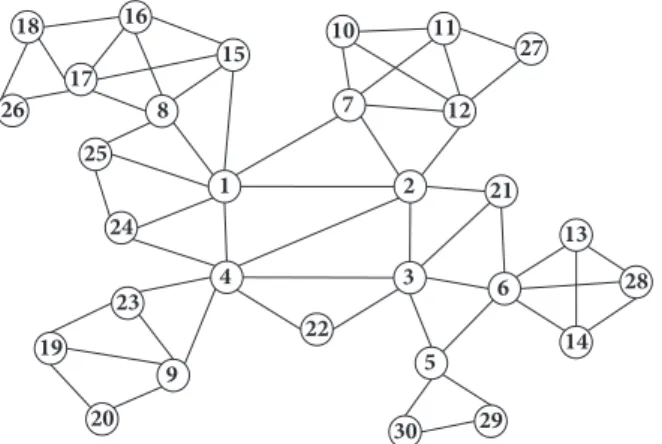
21 30 22 23 24 25 26 27 28 29 1 2 3 4 5 6 7 8 9 10 11 12 13 14 15 16 17 18 19 20
Figure 7: An example network topology of 30 mesh routers.
(iv) The number of route discoveries as the total num-ber of flooding-based route discovery operations throughout the simulation
5.1. Simulation Settings. We evaluate the proposed scheme
and the existing work using ns-3 network simulator [19]. Based on the usage of WMNs in practice as described in [20], mesh routers are connected with each other using multiple IEEE 802.11g interfaces with 11 Mbps bandwidth and 2 ms delay. Mesh clients equipped with one IEEE 802.11g interface use a 2.4 GHz channel, and mesh routers have three network interfaces, one for connecting mesh clients and others for connecting with neighbor mesh routers. Mesh routers use three different channels for minimizing interference. The transmission range of all wireless channels is set to 120
meters. In the two-dimensional area of 500 × 500 m2, we
place 30 mesh routers with uniform random distribution. We generate five different network topologies and obtain the average results with the same data point of simulations. Each mesh router has connections with its neighbor mesh routers based on their transmission range. We assume that all mesh routers are connected without network partitions. One of the network topologies of mesh routers we generated is illustrated in Figure 7. For mesh clients, we apply node mobility using the random waypoint model with a speed between zero to five m/s and a 10-second pause time.
We generate multiple application flows using a random-ized sets of sources and destinations, in which destination nodes are different from their source and uniformly dis-tributed in the network as well as done in the literature [8, 11]. For our experiments, we use a live video streaming application which has four QoS constraints: bandwidth, delay, delay jitter, and packet loss rate. Whether a flow satisfies its bandwidth requirement can be evaluated by application goodput. The goodput of a live video streaming application is the amount of playable data arriving at the application layer of the destination per unit time. If a data frame arrives at the destination later than its play time, then the data is discarded by the application. The size of data packets is 1024 bytes, and we vary the packet sending rate per unit time for making different conditions of network congestion. For
Table 1: Simulation parameters.
Network simulator ns-3.26
Simulation time 100 seconds
Simulation area 500× 500 m2
Number of mesh routers 30
Number of mesh clients 20
Node distribution Uniform random
Mesh routers radio model IEEE 802.11g
Mesh routers radio channels 1, 6, 11
Transmission range 120 m
Number of interfaces (mesh routers) 3 Number of interfaces (mesh clients) 1 Mesh client mobility model Random waypoint
Mobility maximum speed 0,5,10,15,20 m/s
Mobility pause time 10 seconds
Link capacity 11 Mbps
Link propagation delay 2 ms
Number of application flows 10-20
Application packet size 1024 bytes
Application packet sending rate 150-280 packets/s
Local repair scope 1, 2
Evaluation function interval 1 second
QoS degradation threshold 3
live streaming applications, we set the QoS requirement of
each flow as 𝑐1 =1.229Mbps to 2.294Mbps, 𝑐2 = 100ms,
𝑐3 = 100ms, and 𝑐4 = 0.1, where the set of constraints is
{𝑐1=bandwidth, 𝑐2 =delay, 𝑐3=jitter, 𝑐4=packet loss rate}. The
bandwidth constraint is varying based on the packet sending rate of each flow from 150 to 280 packets/s.
The simulation time is 100 seconds, and all application flows randomly start and stop within the simulation time while keeping a condition that the session time is at least 50 seconds. We run 20 repetitions for each individual setting of simulation and average their results. In the proposed scheme, a local repair scope based on the TTL value of a FAREQ is varying with one and two, which we call 1 and TTL-2, respectively. The interval of a link evaluation function for detecting QoS degradation is set to one second. The QoS degradation threshold of each link is fixed with three. Major simulation parameters are described in Table 1.
5.2. Application Goodput. In this section, we compare the
goodput of live video streaming applications for the proposed scheme and the existing work. We aggregate the goodput of all flows for the live video streaming application in the network. Figure 8 shows the aggregate goodput of the existing work and the proposed schemes with two different local repair scopes. Both the proposed schemes outperform the existing work for all number of flows we tested, showing the most performance gain of 16.6% when 17 flows are generated. The tendency of the goodput gap between the existing work and the proposed scheme gets increasing when more flows are generated. This means that the increasing number of flows incur more congestion, and the difference of resolving
1000 1200 1400 1600 1800 2000 2200 2400 A ggr ega te G o o d p u t (k b ps) Existing Work Proposed-TTL1 Proposed-TTL2 11 12 13 14 15 16 17 18 19 20 10 Number of flows
Figure 8: The goodput of the proposed scheme and the existing work with varying number of flows.
A ggr ega te G o o d p u t (k b ps) 1200 1400 1600 1800 2000 2200 2400 2600 150 160 170 180 190 200 210 220 230 240 250 260 270 280 Packet sending rate (packets/s)
Existing Work Proposed-TTL1 Proposed-TTL2
Figure 9: The goodput of the proposed scheme and the existing work with 16 flows under varying packet sending rates.
the congestion leads to the performance gap. The existing work performs route discovery for every QoS degradation while the proposed scheme runs local repair when there are candidate detour paths nearby the QoS-degraded link. Because route discovery affects application session and takes longer time than the local repair we proposed, the goodput of the existing work gets reduced when more route discovery occurs. Figure 9 illustrates the aggregate goodput of the proposed scheme and the existing work with different packet sending rates per flow if the number of flows is fixed to 16. The packet sending rate indicates the bandwidth requirement of each application flow. The proposed scheme outperforms the existing work with up to 19.6% goodput gain for TTL-2. As the bandwidth consumption of each flow increases, the probability of congestion with other overlapping flows on the
0 500 1000 1500 2000 2500 0 5 10 15 20 Mobility speed (m/s) Existing work Proposed-TTL1 Proposed-TTL2 A ggr ega te G o o d p u t (k b ps)
Figure 10: The goodput of the proposed scheme and the existing work with 16 flows under varying maximum speed of mesh clients.
same link also increases. Since such congestion is resolved with lower cost and shorter time in our proposed scheme, resulting goodput becomes higher than the existing work where route discovery is performed for every congestion. Figure 10 shows the goodput of the proposed scheme and the existing work with the varying maximum speed of mesh clients from zero to 20 m/s. We fix the number of application flows to 16. As the mobility increases, the application sessions experience more disconnection and route discovery is per-formed more frequently. Due to the mobility, existing flows also get affected by newly discovered paths due to congestion. The proposed scheme recovers congested flows more rapidly than the existing work, gaining up to 27% higher goodput. For different TTL values in the proposed scheme, the scheme with TTL-2 outperforms the case of TTL-1 because the local repair with a one-hop scope did not find any detour path for some degraded links. If there is no detour path, route discovery is triggered for the flow which failed the local repair. On the other hand, the proposed scheme with TTL-2 can search a detour path from neighbors within two hops, and the probability of finding a detour path becomes higher than TTL-1.
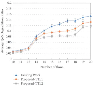
5.3. QoS Degradation Ratio. We measure the QoS
degrada-tion ratio of each flow with the proposed scheme and the existing work, varying the number of flows in the network. Figure 11 illustrates changes in the average QoS degradation ratio of all flows in the network. The proposed scheme outperforms the existing work in most cases showing up to 39.6% reduction for TTL-2 with 17 flows. The proposed scheme with TTL-1 shows similar results with the existing work when the number of flows is less than or equal to 12. This is because the local repair with the information of only one-hop neighbors fails for some cases which lead to route discovery. The gap of QoS degradation ratio between the proposed scheme (TTL-2) and the existing work increases until 18 flows and gets closer in 19 and 20 flows where
Existing Work Proposed-TTL1 Proposed-TTL2 11 12 13 14 15 16 17 18 19 20 10 Number of flows 0 0.02 0.04 0.06 0.08 0.1 0.12 0.14 0.16 0.18 0.2 A verag e Q oS D egrada tio n R atio
Figure 11: The QoS degradation ratio in a general scenario with different number of flows.
0.3 0.35 0.4 0.45 0.5 0.55 0.6 0.65 0.7 0 5 10 15 20 Q oS D egrada tio n R atio Mobility speed (m/s) Existing work Proposed-TTL1 Proposed-TTL2
Figure 12: The QoS degradation ratio with 16 flows under varying maximum speed of mesh clients.
the network becomes saturated. This is because the QoS degradation of some flows cannot be recovered by local repair, or the number of local repairs for the flows exceeds the maximum local repair threshold per flow. Then those flows have an only option to perform route discovery to handle QoS degradation, the same as the existing work. But the proposed scheme still outperforms the existing work for all cases because some other flows are recovered by local repair. Figure 12 depicts changes in the average QoS degradation ratio of 16 flows with varying maximum speed of mesh clients. Due to the movement of mesh clients, some application sessions starting from the moving nodes are disconnected and recovered by route discovery for both the existing work and the proposed scheme; thereby overall QoS degradation ratio is increased by the movement speed
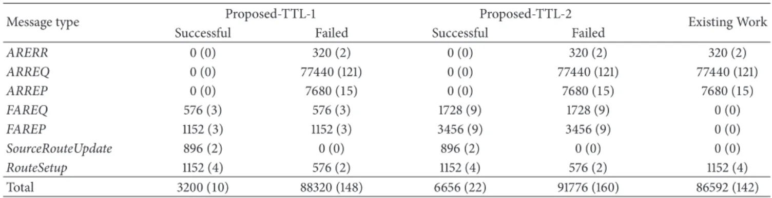
Table 2: The size of control messages generated for handling one QoS degradation. The number in the parenthesis means the number of control messages.
Message type Proposed-TTL-1 Proposed-TTL-2 Existing Work
Successful Failed Successful Failed
ARERR 0 (0) 320(2) 0 (0) 320(2) 320(2) ARREQ 0 (0) 77440 (121) 0 (0) 77440 (121) 77440 (121) ARREP 0 (0) 7680(15) 0 (0) 7680(15) 7680(15) FAREQ 576(3) 576(3) 1728(9) 1728(9) 0 (0) FAREP 1152(3) 1152(3) 3456(9) 3456(9) 0 (0) SourceRouteUpdate 896(2) 0 (0) 896(2) 0 (0) 0 (0) RouteSetup 1152(4) 576(2) 1152(4) 576(2) 1152(4) Total 3200(10) 88320 (148) 6656(22) 91776 (160) 86592 (142) 0 5 10 15 20 25 30 35 40 N um b er o f Ro u te Dis co ver y Existing Work Proposed-TTL1 Proposed-TTL2 11 12 13 14 15 16 17 18 19 20 10 Number of flows
Figure 13: The number of route discovery in a general scenario with different number of flows.
of mesh clients. Except such route discovery, the proposed scheme recovers congested flows with local repair, reducing up to 5.8 percent point. Figure 13 shows the number of route discoveries with varying number of flows. As the QoS degradation ratios of the existing work and the proposed scheme with TTL-1 are similar for 10-12 flows, the numbers of route discovery of those two schemes are also similar for the same conditions. One can find that there is a tendency that the more the number of route discoveries, the more the QoS degradation ratio of flows. Figure 14 shows the number of route discoveries with varying maximum speed of mesh clients where 16 flows are running on the network. Overall, due to the movement of mesh clients which are source nodes of some flows, the number of route discoveries increases with the node speed. For the existing work, although some flows are not disconnected by mobility, they get rediscovered due to QoS degradation generated by other flows. Since the proposed scheme recovers those flows with local repair, the number of route discoveries is reduced up to 27.9% at the maximum speed of 5 m/s. N um b er o f Ro u te Dis co ver y 0 10 20 30 40 50 60 70 80 0 5 10 15 20 Mobility speed (m/s) Existing work Proposed-TTL1 Proposed-TTL2
Figure 14: The number of route discoveries with 16 flows under varying maximum speed of mesh clients.
5.4. Routing Overhead. We measure the routing overhead
of the existing work and the proposed scheme in terms of the amount of control messages for routing operations throughout a simulation. We obtain the routing overhead by dividing the total amount of packets generated with the amount of routing control messages, where both values are represented in bytes. We exclude control messages for link quality measurement which shows no difference among all schemes (i.e., they are basically generated for one-hop neighbors). We measure the amount of control messages for recovering a QoS-degraded routing path in the proposed scheme and the existing work. Under the same environment of the motivating scenario in Figure 1, we artificially generate QoS degradation for the link 3-4 and check the amount of control messages generated until the route is recovered by local repair or route discovery. For the proposed scheme, we consider the case when no detour path is found.
Table 2 shows the amount of routing control mes-sages for the proposed schemes with different TTL val-ues and the existing work in bytes. The number in the
100000 150000 200000 250000 300000 350000 Ro u tin g mess ag es (kilob yt es) Existing Work Proposed-TTL1 Proposed-TTL2 11 12 13 14 15 16 17 18 19 20 10 Number of flows
Figure 15: The amount of routing control messages with different number of flows.
parenthesis indicates the number of control messages gen-erated. The Application-Aware Route Request (ARREQ) and Application-Aware Route Reply (ARREP) messages are extension to Route Request (RREQ) and Route Reply (RREP) messages used for distance vector-based ad-hoc routing protocols such as AODV [21] and DSR [22]. The ARREQ message indicates a route discovery message that floods over the network by broadcast, which contains a flow information, QoS requirements as constraints, an end-to-end path quality field for accumulating link quality values of multiple hops. The ARREP message is the reply of an ARREQ generated by a destination node including the end-to-end path quality. If local repair is successfully performed, the amount of control messages are much smaller than the existing work, consum-ing up to 7.6% of the control messages for route discovery. In the proposed scheme, an intermediate node which detects QoS degradation unicasts FAREQ messages to the subset of its neighbors which are common neighbors of the degraded link. The neighbors receiving the FAREQ only generate an
FAREP message and send it to the intermediate node. The
result of local repair is also shared through the routing path from the intermediate node to the source
(SourceRouteUp-date) and the destination (RouteSetup). Likewise, a minimum
number of control messages are generated and delivered by unicast. When local repair in our proposed scheme fails to find any alternative detour path, the proposed scheme generates slightly more control messages than the existing work. The Failed column of each proposed scheme shows that ARERR, ARREQ, and ARREP messages are generated the same as the existing work. This is because the control messages for local repair and route discovery are aggregated. However, such failure does not always occur in the network, and our simulation results with randomized environments show that the local repair is effective for reducing the routing overhead.
Figure 15 illustrates the amount of routing control mes-sages in bytes as increasing the number of flows in the
0 5 10 15 20 Mobility speed (m/s) Existing work Proposed-TTL1 Proposed-TTL2 0 50000 100000 150000 200000 250000 300000 350000 400000 450000 500000 Ro u tin g M ess ag es (kilob yt es)
Figure 16: The amount of routing control messages with varying maximum speed of 16 mesh clients.
network with 30 mesh routers. The proposed scheme out-performs in all cases reducing the control overhead up to 33% for TTL-2 compared with the existing work. With less than 14 flows, the gap between the proposed scheme and the existing work is small because QoS degradations do not occur frequently. When the network becomes congested more than or equal to 14 flows, the existing work triggers route discovery more than the proposed scheme as shown in Figure 13, which results in more routing control messages. When the network gets saturated with more than or equal to 19 flows, the amount of routing control messages of the proposed scheme increases because it is difficult to find alternative detour paths. Figure 16 depicts the amount of routing messages under different maximum speed of mesh clients with 16 flows in the network. Due to increased number of route discovery shown in Figure 14, overall amount of routing messages is increased with the mobility speed. The proposed scheme performs local repair for flows which are not disconnected by mobility, and up to 28.1% of routing messages are saved preventing unnecessary route discovery for resolving congestion.
Figure 17 shows the routing overhead incurred with increasing packet sending rates of each flow when the number of flows is fixed to 16. The routing overhead is the portion of routing control messages for all generated packets in the network. In general, the routing overhead of all schemes go down as the packet sending rate increases because the amount of data packets generated per unit time increases linearly. At the 200 packets/s, QoS degradation increases due to network congestion. From the point, the existing work incurs more number of route discoveries, and the amount of control messages for such route discovery affects the routing overhead to increase. The proposed scheme shows lower routing overhead from 200 packets/s because of smaller number of route discoveries than the existing work. The proposed scheme reduces routing overhead up to 25.11% at 250 packets/s with TTL-2. The gap of routing overheads for the existing work and the proposed scheme gets closer after
Existing Work Proposed-TTL1 Proposed-TTL2
160 170 180 190 200 210 220 230 240 250 260 270 280 150
Packet sending rate 0.04 0.06 0.08 0.1 0.12 0.14 0.16 0.18 0.2 0.22 0.24 Ro u tin g O verhe ad
Figure 17: The routing overhead of 16 flows in the network with varying packet sending rates per flow.
260 packets/s because the overall network becomes saturated and it is getting difficult to find alternative detour paths with local repair.
5.5. Discussions. A wireless channel is a shared medium
where one device can transmit signal at a time. If three devices are consecutively connected with two wireless links using the same channel in two hops, those two links cannot be used at the same time for transmission due to signal interference. This means that if one link is used by a certain application traffic, the available bandwidth of another neighboring link is also reduced. In this paper, we assume that the available bandwidth between any pair of mesh routers is not affected by other neighboring links because our focus does not cover the interference modeling of wireless links. This is a com-plementary work that can be applied to available bandwidth measurement. Moreover, since mesh routers are generally assumed to be equipped with multiple radio interfaces with multiple orthogonal channels, existing solutions on channel assignment can be exploited further [23].
The proposed protocol may incur higher cost in terms of maintaining control messages and contexts than existing multi-constrained routing protocols but the evaluation result shows that it is worthy to support fast route recovery in a distributed manner. Because a mesh router is fundamentally an embedded system with limited computing resources, one can have questions on the load of supporting the proposed scheme. The capacity of wireless mesh routers are getting improved equipping multiple cores and more memory spaces, and functionalities for supporting QoS are continuously added into commodity devices. The proposed routing protocol is compatible with existing connectivity-based routing information which additionally handles infor-mation of flows and their contexts (QoS requirements, path quality, etc.). We can quickly search and identify data using flow information as an identifier, and the flow structure can be used as a key of hashing for fast and cost-efficient search.
Moreover, as shown in simulation results, the proposed scheme can actually reduce the total amount of control messages on realizing QoS-aware routing.
Another concern is the integration with Software Defined Networking (SDN) using programmable networking princi-ples. SDN is being actively applied to WMNs for its flexible and intelligent control of mesh routers considering QoS [24– 26]. Since the proposed local repair-based multi-constrained routing protocol is based on existing link quality measure-ment schemes and the extension of distance vector routing principles, our scheme can be easily applied to the SDN environment. One thing we need to concern is that the local repair operation is based on distributed routing. If an SDN controller is a centralized entity, every single context of mesh routers required for deciding an optimal alternative detour path needs to be shared with the controller, which would dramatically increase control overhead. However, by applying the concept of distributed controllers [24], some specific network contexts which are only required for neighboring mesh routers can be localized reducing the cost.
6. Related Work
Finding a routing path with multiple different QoS metrics has been actively studied. It is known that the problem of finding an optimal path with multiple additive constraints is NP-Hard [3, 27, 28]. In order to reduce the time complexity, some approaches have defined a single aggregated metric calculated from multiple metrics [29, 30]. Although they reduce the search space the same as well-known shortest routing algorithms, this might not satisfy the requirement of applications because the single aggregated value may not guarantee the constraint of some specific metrics. In order to make a path with the best single aggregated value which could be also in the set of feasible paths, a number of heuristic algorithms have been proposed [2–4, 8, 9, 12, 13, 31] in which nonlinear functions are generally utilized. Since there may exist several feasible paths between the same source and destination pair, the routing protocol needs to select one of them. Such selection is done by using an optimization function or a utility function which is similar to the single aggregated metric. The type of optimization functions includes the weighted sum of all metrics [32, 33] and the utilization of only one or some of metrics based on priority [2, 3, 12]. In order to support different application requirements, authors in [11] define multiple optimization functions each of which emphasizes different parameters based on different purposes such as energy efficiency, smaller interference, or the shortest path length.
All aforementioned works mainly focus on discovering a new routing path satisfying multiple constraints. However, handling the QoS degradation of already-established paths is not considered. Most works use route discovery for the routing path that violates the QoS requirement of its corresponding application. Another option for recovering such QoS-degraded routing path is local repair. Local repair approaches have been proposed mainly in mobile ad-hoc network (MANET) routing protocols [21, 22]. The major purpose of local repair is to find a detour path which