40-2 / J.-I. Lee
• IMID 2009 DIGEST
Abstract
We have fabricated transparent white organic light emitting diodes (WOLEDs) for lighting application. The structure property relationship of hybrid WOLEDs has been investigated and optimized devices showed high efficiency. Introduction of transparent cathode of LiF/Al/Ag into the hybrid WOLED led highly efficient WOLED with good transparency.
1. Introduction
Organic light emitting diodes (OLEDs) are very promising candidates for next generation solid state lighting sources to substitute conventional incandescent bulbs and fluorescent lamps. OLEDs can provide energy efficient lighting as well as environmentally friendly lighting sources. Power efficiencies of OLEDs have already outperformed those of incandescent bulbs and closed to those of fluorescent lamps. However, some technical issues including lifetime and production cost should be solved to penetrate in the market.
OLEDs technology offers more than energy efficient and environmentally friendly lighting sources. OLEDs also have unique form factors allowing flat and thin lighting sources covering square meters. Moreover, OLEDs can provide revolutionary lamp properties such as transparent, color tunable and flexible lighting sources, which also offer much more
freedom in designing lighting.1-3
In Electronics and Telecommunication Research Institute (ETRI), we have interested in development of transparent white OLEDs as well as conventional bottom emission white OLEDs. Intensive device engineering has been performed to fabricate efficient white OLEDs using phosphorescent and fluorescent materials. Moreover, the optimizations of electrode structures to fabricate large area lighting sources with good uniformity as well as out-coupling structures
have been carried out. In this presentation, the structure and property relationships in the transparent cathode and WOLED will be discussed.
2. Experimental
The basic structure of the hybrid white OLED was ITO/hole transporting layer (HTL)/phosphorescence emitting layers (PH-EMLs)/interlayer/fluorescence emitting layer (FL-EML)/electron transporting layer (ETL)/cathode as shown in the figure 1. Fluorescence materials were used for blue emission and phosphorescence materials were used for other colors spanning from green to red. To prevent triplet quenching process, interlayer was inserted between FL-EML and PH-EMLs. As a cathode, LiF(1 nm)/Al(100 nm) layers were employed for a bottom emission device and LiF (1 nm)/Al(1.5 nm)/Ag(15 nm)/NPB(50 nm) layers were used for a transparent OLEDs. To improve transmittance of transparent OLEDs.
Fig. 1. The basic structure of OLED used in this study.
ITO was cleaned by the standard oxygen plasma treatment. The OLED grade materials were purchased and used without further purification. All organic layers were deposited in a high vacuum chamber
Highly efficient and transparent white OLED for lighting
Jeong-Ik Lee*, Jonghee Lee, Joowon Lee, Jae-Heon Shin, Hye Yong Chu
OLED lighting team, ETRI, Daejeon, Korea
Phone: 84-42-860-1166, E-mail: jiklee@etri.re.kr
40-2 / J.-I. Lee
IMID 2009 DIGEST •
below 5 x 10⁻⁷ torr. The OLEDs were transferred
directly from vacuum into an inert environment glove-box, where they were encapsulated using a UV-curable epoxy, and a glass cap with a moisture getter. The electroluminescence spectrum was measured using a Minolta CS-1000. The current-voltage (I-V) and luminescence-voltage (L-V) characteristics were measured with a current/voltage source/measure unit (Keithley 238) and a Minolta CS-100. The transmittance was characterized using Hitachi 3000 spectrophotometer.
3. Results and discussion
The hybrid white OLED with blue fluorescence materials and phosphorescence materials for other colors has been believed to offer more stable white light than the phosphorescence white OLED. We have tested various blue fluorescence materials and chosen a host and a dopant for the hybrid white OLED. Phosphorescence emitting layer (PH-EMLs) were introduced between the HTL and the blue FL-EML. The interlayer between the FL-EML and the PH-EMLs prevents energy transfer between two layers and lead to balanced emissions as well as good light emitting efficiency. The charge trapping in the PH-EMLs also plays important role in obtaining balanced emissions from the both light emitting layers.
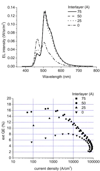
Firstly, we have optimized device structure based on bottom emission device. The effect of the interlayer thickness was investigated with a fluorescence blue and a phosphorescence green layers. As shown in the figure 2, device characteristics were almost same except the device without the interlayer. The device without interlayer showed weaker phosphorescence (green emission) and stronger fluorescence (blue emission) than other devices with the interlayer. We believe that the interlayer might block hole transport from the PH-EML to the FL-EML. As for the effects of the interlayer on the prevention of energy transfer, it seemed that 50 Å of the interlayer successfully prevented energy transfer between the PH-EML and the FL-EML. When there was no interlayer, the efficiency close to the efficiency of the blue fluorescence only device was obtained although there was partial contribution from the phosphorescence green emission, which indicated that there was some energy transfer quenching from the PH-EML to the triplets of the FL-EML.
We have also investigated dopant effects on device performance. The thickness of the interlayer was 50 Å and a green dopant or an orange dopant was
400 500 600 700 800 0.00 0.02 0.04 0.06 0.08 0.10 0.12 0.14 Interlayer (A) 75 50 25 0 E L i n te n s ity (W /s r/m 2 ) Wavelength (nm) 10 100 1000 10000 100000 0 2 4 6 8 10 12 14 16 18 20 Interlayer (A) 75 50 25 0 e x t QE (%)
current density (A/cm2)
Fig. 2. The electroluminescence spectra and the external quantum efficiency profiles of the hybrid OLED with a blue fluorescence and a green phosphorescence layers.
employed as a dopant of the PH-EMLto study the relationship between dopant property and device characteristics. As shown in the figure 3, they exhibited very different emission characteristics. The device with a green phosphorescence dopant exhibited stronger green emission than blue emission while the device with an orange phosphorescence dopant did weaker orange emission. These results can be explained by charge trapping ability of phosphorescence dopant. As for the green dopant, it has low HOMO level than the orange dopant shown in the figure 1. Therefore, strong hole trapping or hole blocking in the PH-EML is expected, which results in strong phosphorescence green emission. On the contrary, the orange dopant has high HOMO level and close to that of host material, which results in weak or no hole trapping or hole blocking in the PH-EML and
40-2 / J.-I. Lee
• IMID 2009 DIGEST
recombination shift to the FL-EML. To obtain balanced emission from the FL-EML and the PH-EML, it is very important to control the charge trapping or blocking and also the interlayer in the hybrid white OLED.
400 500 600 700 800 0.00 0.02 0.04 0.06 0.08 0.10 0.12 0.14 0.16 green orange EL intensity (W /sr/m 2 ) Wavelength (nm) 10 100 1000 10000 100000 0 2 4 6 8 10 12 14 16 18 20 green orange ex t QE (% )
current density (A/cm2)
Fig. 3. The electroluminescence spectra and the external quantum efficiency profiles of the hybrid OLED with a blue fluorescence and a green or an orange phosphorescence layers.
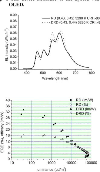
Based on the above results, we have fabricated optimized devices using the blue FL-EML and the PH-EML containing a green, an orange, and red as shown in the figure 4. In this device structure, we have used two different red dopants having different emission maximum, but the device performances are very similar to each other. The electroluminescence spectra of the devices are shown in the figure 5. We have successfully obtained a white light emission with 1931 CIE coordinates of (0.43, 0.42) and (0.43, 0.44), CRI 80, and CCT 3200-3300 K at a luminance of
1000 cd/m2. Highly efficient hybrid WOLEDs with
external and power efficiencies of 15 %, and 25-27 lm/W were achieved without any out-coupling
enhancement at a luminance of 1000 cd/m2 with a
driving voltage of about 4.3 V.
Fig. 4. The device structure of the hybrid white OLED. 400 500 600 700 800 0.00 0.01 0.02 0.03 0.04 0.05 0.06 0.07 0.08 0.09 RD (0.43, 0.42) 3290 K CRI >80 DRD (0.43, 0.44) 3280 K CRI >80 E L intensity (W/sr/m 2 ) Wavelength (nm) 10 100 1000 10000 100000 0 4 8 12 16 20 24 28 32 36 40 RD (lm/W) RD (%) DRD (lm/W) DRD (%) EQE ( % ), effica cy ( lm/W) luminance (cd/m2)
Fig. 5. The electroluminescence spectra and the external quantum efficiency and the luminous efficacy profiles of the hybrid white OLEDs.
40-2 / J.-I. Lee
IMID 2009 DIGEST •
To fabricate transparent white OLED, the cathode structure was changed. There have been lots of reports about the transparent cathode structure, and most of them are composed of an electron injection layer, a conductive layer, and a capping layer. Among them, the cathode structure with LiF for an electron injection layer, thin Al and Ag for a conductive layer and an organic layer for a capping layer is a general method to be fabricated and offer fairly good device performance. The optimized thicknesses of each layer have been investigated and found to be 1 nm of LiF, 1.5 nm of Al, 15 nm of Ag, and 50 nm of NPB, respectively. We could obtain about 60 % transmittance when we used the transparent cathode structure of LiF/Al/Ag/NPB for transparent OLEDs with conventional glass encapsulation.
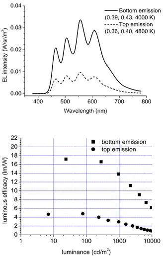
400 500 600 700 800 0.00 0.01 0.02 0.03 0.04 Bottom emission (0.39, 0.43, 4000 K) Top emission (0.36, 0.40, 4800 K) E L in te nsi ty (W /s r/ m 2 ) Wavelength (nm) 1 10 100 1000 10000 0 2 4 6 8 10 12 14 16 18 20 22 bottom emission top emission luminous efficacy (lm/W) luminance (cd/m2)
Fig. 6. The electroluminescence spectra and the and the luminous efficacy profiles of the transparent hybrid white OLED.
We applied the transparent cathode structure of LiF/Al/Ag/NPB to the hybrid white OLED and the device characteristics were shown in the figure 6. The
top emission spectrum showed higher CCT and lower x and y value in CIE coordinates compared with the bottom emission spectrum. The CIE coordinates and CCT of the bottom emission were (0.39, 0.43) and 4000 K while those of the top emission were (0.36, 0.40), 4800 K, respectively. The different characteristics between the bottom and top emission might be attributed to the different micro-cavity effects of the bottom and top emission directions. The CRI’s of both bottom and top emissions reached over 80. From the emission intensity, we found that the bottom emission of the transparent WOLED exhibited about 3.5 times higher external quantum efficiency. The power efficiency for the bottom and the top directions were 14 and 3 lm/W, respectively, at a
luminance of 1000 cd/m2. In addition, the total power
efficiency of the transparent WOLED reached 19
lm/W at a total luminance of 1000 cd/m2.
4. Summary
The hybrid white OLED has been fabricated using the blue FL-EML and the green/orange/red PH-EML and 15 % of EQE and 25-27 lm/W of luminous
efficacy has been achieved at 1000 cd/m2. We have
also fabricated the transparent hybrid white OLED and 19 lm/W was obtained at a total luminance of
1000 cd/m2 with about 60 % of transmittance at 550
nm.
Acknowledgement
This work was supported by the IT R&D program of MKE/KEIT [2009-F-016-01, Development of Eco-Emotional OLED Flat-panel Lighting]. Authors gratefully acknowledged Ms. K. -I. Song and Ms. S. J. Lee (ETRI) for assistance with OLED fabrication and measurement. Authors also thank for kind material supplies from SFC co. in Korea.
5. References
1. N. Ide, H. Tsuji, N. Ito, H. Sasaki, T. Nishimori, Y. Kuzuoka, K. Fujihara, T. Miyai, T. Komoda, Proc.
of SPIE, 7051, p.705119-1 (2008).
2. V. Van Elsbergen, H. Boemer, H.-P. Lobl, C. Goldmann, S. P. Grabowski, E. Young, G. Gaertner, H. Greiner, Proc. of SPIE, 7051, p.70511A-1 (2008).
3. G. Schwartz, S. Reineke, T. C. Rosenow, K. Walzer, K. Leo, Adv. Funct. Mater., 19, 1 (2009).