Columnar-Structured Low-Concentration Donor Molecules in Bulk
Heterojunction Organic Solar Cells
Ji-Won Seo,
†,‡,#Jong Hun Kim,
†,∥Mincheol Kim,
‡,§Seon-Mi Jin,
⊥Sang-Hoon Lee,
†,‡Changsoon Cho,
†,‡Eunji Lee,
⊥Seunghyup Yoo,
‡,§Jeong Young Park,
†,∥and Jung-Yong Lee
*
,†,‡†Graduate School of Energy, Environment, Water, and Sustainability (EEWS),‡Graphene Research Center, KI for NanoCentury, and §Department of Electrical Engineering, Korea Advanced Institute of Science and Technology (KAIST), 291 Daehak-ro, Yuseong-gu, Daejeon 34141, Republic of Korea
∥Center for Nanomaterials and Chemical Reactions, Institute for Basic Science (IBS), 291 Daehak-ro, Yuseong-gu, Daejeon 34141, Republic of Korea
⊥Graduate School of Analytical Science and Technology, Chungnam National University, 99 Daehak-ro, Yuseong-gu, Daejeon 34134, Republic of Korea
*
S Supporting InformationABSTRACT: We investigate the arrangement of donor molecules in vacuum-deposited bulk heterojunction (BHJ) 1,1-bis-(4-bis(4-methyl-phenyl)-amino-phenyl)-cyclohexane (TAPC):C70-based organic solar cells (OSCs). Even a low
dose of donors (∼10%) forms columnar structures that provide pathways for efficient hole transport in the BHJ layer; however, these structures disappear at donor concentrations below 10%, generating disconnected and isolated hole pathways. The formation of columnar donor structures is confirmed by the contrast of the contact potential difference,
measured by Kelvin probe force microscopy, and by the trap-assisted charge injection at low donor concentrations. The mobility of electrons and holes is well balanced in OSCs owing to the preservation of the hole mobility at such low donor concentrations, consequently maximizing the internal quantum efficiency of the OSCs. A high power conversion efficiency of 6.24% was achieved in inverted TAPC:C70(1:9) OSCs.
■
INTRODUCTIONIn general, to achieve efficient exciton dissociation in polymer or small molecular bulk heterojunction (BHJ) organic solar cells (OSCs), the donor to acceptor volume ratio should range from 4:1 to 1:4.1−5For instance, for a low volume of donors, below the optimum donor concentration, the hole transport is interrupted by the phase aggregation of active materials and the imbalanced hole and electron mobility increases bimolecular charge recombination.1,6,7
Recently, vacuum-deposited small molecular OSCs (SMOSCs) with low donor concentration (<20 vol %) were reported to exhibit considerably high efficiency.8−11 The exciton dissociation efficiency in BHJ layers is enhanced when ample donor/acceptor interfaces are generated through the random mixing of donor and acceptor materials.12 Interestingly, it has been demonstrated that the internal quantum efficiency (IQE) is maximized at comparatively low donor concentrations, which creates fewer donor/acceptor interfaces.8,9
Moreover, few studies exist on the hole-transport pathways and how these are actually formed despite the low dose of donor molecules. Holes could be transported along the fullerene when fullerene acts as a donor material.13However,
a very low hole mobility in fullerene as an acceptor material in BHJfilm compared to that in 1,1-bis-(4-bis(4-methyl-phenyl)-amino-phenyl)-cyclohexane (TAPC) would cause an electron and hole (e−h) imbalance and, consequently, considerable charge recombination, which would result in low power conversion efficiency (PCE).8,14−16Therefore, further research is necessary on the correlation between the balance of e−h mobility and the morphology variations caused by donor concentration changes, which eventually affect charge recombi-nation and transport.7Furthermore, the morphological analysis in bulk heterojunction (BHJ) film is necessary to design the structure of small molecular organic electronics as well as OSCs to achieve the desired electrical and morphological character-istics of organic electronics.
As the thermally codeposited donor and acceptor materials of SMOSCs are stacked sequentially on substrates, they form horizontal and vertical molecular arrangements in BHJ films without excessive phase aggregation, as in polymer BHJ films.17,18
Moreover, many small molecule materials for Received: October 27, 2017
Accepted: January 15, 2018
Published: January 24, 2018
Article Cite This:ACS Omega 2018, 3, 929−936
This is an open access article published under an ACS AuthorChoice License, which permits copying and redistribution of the article or any adaptations for non-commercial purposes.
Downloaded via KOREA ADVANCED INST SCI AND TECHLGY on June 24, 2018 at 14:58:51 (UTC).
thermally evaporated OSCs showed that low donor concen-tration is suitable for high PCE, which supports the similar morphological tendency of various small molecule materials in BHJfilms as a function of donor concentration.8,9,19Therefore, we can speculate that donors with low concentration might be sufficient to form percolated pathways for efficient hole transport.9,19However, few confirmations exist of the formation of such columnar-structured donors because both donor and acceptor organic materials mainly consist of light atoms, such as carbon and hydrogen; these do not exhibit sharp contrast between donors and acceptors in high-resolution transmission electron microscopy (TEM) or two-dimensional-mapping energy dispersive X-ray spectroscopy, hindering the analysis of columnar-structured donors.
In this study, we focus on the morphological variation of donors in BHJfilms as a function of donor concentration. For the first time, we verify and visualize that hole-transporting pathways are formed in a columnar structure across the BHJ layer when the donor concentration is larger than 10%. Moreover, the columnar-structured donor can be measured by ultrahigh resolution Kelvin probe force microscopy (KPFM) because donors and acceptors in BHJs have different energy levels. Finally, we investigate the balance of e−h mobility with respect to the donor concentration in BHJ OSCs for higher PCE.
■
RESULTS AND DISCUSSIONLow-Concentration Donor OSCs. In this work, TAPC (the donor) and C70 fullerene (C70) (the acceptor) were
coevaporated to construct a BHJ layer in inverted BHJ SMOSCs. Figure S1 shows the extinction coefficients of TAPC and C70, revealing that TAPC does not absorb visible light; in contrast, C70absorbs incident light in the overall visible
wavelength range below 800 nm. Hence, only the absorption and exciton dissociation of C70 can be analyzed at all visible
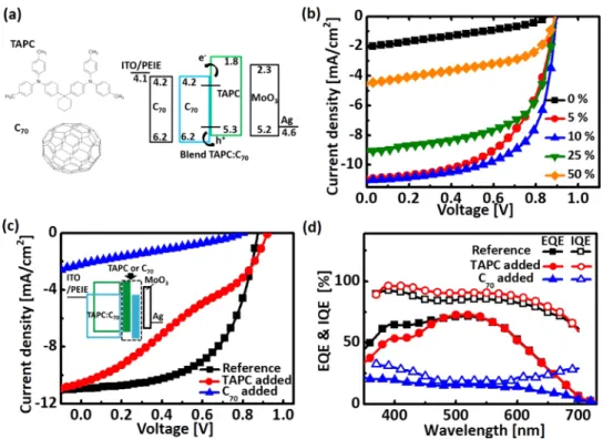
wavelengths with respect to the TAPC concentration.Figure 1a presents the energy level diagram and chemical structures of the TAPC donor in bulk C70acceptor layers; the device structure is glass/indium tin oxide (ITO)/polyethylenimine ethoxylated (PEIE)/C70(10 nm)/TAPC:C70(50 nm)/MoO3(10 nm)/Ag (150 nm).
Figure 1b illustrates the current density−voltage (J−V) characteristics of the inverted TAPC:C70 BHJ SMOSCs with
various concentrations of TAPC. When the TAPC concen-tration begins to decrease from 50%, which is the commonly applied BHJ ratio, the photovoltaic performance, such as the short-circuit current (Jsc) and thefill factor (FF), was enhanced.
The inverted OSC with 10% TAPC displayed an increase of Jsc calculated by external quantum efficiency (EQE) from 4.62 to 11.35 mA/cm2 with increased IQE and absorption, and
resultantly, EQE (Figure S2). The FF of the inverted OSC
Figure 1.Device performance of low-TAPC-concentration inverted SMOSCs. (a) Energy levels of layers of the device. Insets are chemical structures of TAPC and C70. (b) Current density−voltage (J−V) characteristics of the inverted TAPC:C70BHJ OSCs with TAPC concentrations 0, 5, 10, 25,
and 50%. (c) J−V characteristics and (d) external quantum efficiency (EQE) and IQE of the inverted TAPC:C70(1:9) BHJ OSCs with a TAPC or a
C70layer inserted between the BHJ and MoO3layers. Inset of (c): schematic illustration of the devices. Table 1. Photovoltaic Performance of TAPC:C70OSCs as a Function of TAPC Concentration
TAPC concentration (%) Jsc(mA/cm2) V
oc(V) FF PCE (%)
inverted TAPC:C70OSCs 50 4.62± 0.08 0.89± 0.00 0.50± 0.01 2.07± 0.02
25 8.40± 0.58 0.88± 0.01 0.60± 0.02 4.42± 0.28
10 11.35± 0.19 0.90± 0.01 0.61± 0.01 6.24± 0.11
5 10.77± 0.23 0.86± 0.02 0.56± 0.04 5.14± 0.38
0 1.81± 0.12 0.82± 0.04 0.31± 0.02 0.45± 0.05
gradually increased to 0.61 because the e−h mobility was balanced with the decreased recombination of charges due to the improved crystallinity of C70, as revealed inFigure S3 and
Table S1.20,21 As a result, the inverted TAPC:C70 BHJ SMOSCs showed a maximum PCE of 6.24% when the TAPC concentration was 10% (Table 1); the optimum donor concentration is different from that in previous reports based on a normal structure because different predeposited layers under BHJ films (normal OSCs, MoO3, inverted OSCs, C70) and optical electricfield distribution in OSCs can lead to the morphological changes of BHJ and different exciton generation distributions in BHJfilms.8,22,23For comparison, performance of normal TAPC:C70 OSCs as a function of donor
concentration is shown in Figure S4 and Table S2 (see the Supporting Information for more details). When the TAPC concentration was lower than 10%, Jsc decreased despite the
increased absorption of the TAPC:C70layer. Moreover, the FF
also started to decrease partly owing to the largely deteriorated hole mobility, which can cause significant charge recombina-tion.7,24
To check whether the other types of donors show a similar tendency with TAPC donor material, chloroaluminium phthalocyanine (ClAlPc) and tetraphenyldibenzoperiflanthene (DBP) donor-based inverted OSCs were fabricated. As shown in Figure S5 and Table S3, these OSCs showed the highest PCE at 10% donor concentration, confirming that the low donor concentration in BHJfilm is suitable for high efficiency of OSCs.
Columnar-Structured Donor Molecules. In the full-erene-rich BHJ layer, the dissociated free electrons are transported from the C70 to the ITO. However, it is unclear whether holes are transported along the TAPC or C70to the Ag
electrode because a very small dose of donors was intermixed in the C70layer. To investigate where the holes are transported, a bulk C70or TAPC layer (20 nm) was inserted between the BHJ
and MoO3 layers, as shown in Figure S6a and the inset of Figure 1c. When a TAPC layer is added, the holes could be efficiently collected at the Ag electrode regardless of whether they are transported along (i) TAPC or (ii) C70. However, when a C70 layer is added, the holes would be blocked by the
C70layer if they are transported along (iii) TAPC, whereas they would be easily collected at the electrode with transport along (iv) C70. Figure 1c demonstrates the degraded photovoltaic
characteristics observed when a bulk C70 layer was inserted. The IQE showed little change upon inserting a 20 nm-thick TAPC layer compared with the reference device (Figure 1d). This result confirms that the holes were transported mostly through the TAPC rather than the C70. It should be noted that
the absorption spectra of the three types of devices were almost identical, as shown inFigure S6b. The hole mobility of the C70
-added device decreased by up to 2 orders of magnitude, whereas the hole mobility of the TAPC-added device was slightly decreased, indicating that the holes were blocked by the added C70 layer (Figure S6c). The photovoltaic performance and hole mobility of the reference and bulk C70- or
TAPC-added layer devices are summarized inTable S4.
Figure 2a illustrates hypothetical cross-sectional morpholo-gies of the TAPC:C70 BHJ layer as a function of donor
concentration. At 50% TAPC concentration, the TAPC would be well mixed with C70, forming isotropic pathways because the
volume of TAPC is sufficiently high. However, when the concentration of TAPC decreases to 10%, the TAPC is not sufficient to build both the vertical and the horizontal morphology.
Figure S7 and Table S5show that the surface energies (γtotal)
of TAPC and C70 are 30.04 and 31.47 mN/m, respectively, inducing a high interfacial tension of 7.63 mN/m that causes a repulsive force between TAPC and C70.
25
Consequently, the thermally evaporated TAPC and C70 atoms are strongly attracted toward the same types of predeposited atoms,
Figure 2.Vertical and horizontal mobilities of low-TAPC-concentration SMOSCs. (a) Schematic illustration of the cross-sectional morphology and (b) vertical and horizontal hole mobilities of TAPC:C70BHJ layer with TAPC concentrations 10, 25, and 50%. (c) Illustration of a hypothetical
columnar-structured inverted TAPC:C70 BHJ OSC, where C70in the BHJ layer appears transparent.
eventually generating the surface-energy-driven phase separa-tion of TAPC and C70. Hence, the TAPC and C70 atoms are selectively self-assembled, showing the possibility of the formation of vertically penetrating pathways from TAPC, similar to that in columnar structures.18
We measured the vertical and horizontal hole mobilities using hole-only devices and organic thin-film transistors, respectively. As shown in Figure 2b and Table S6, when the concentration of TAPC varied from 50 to 10%, the horizontal hole mobility of TAPC:C70 was further decreased compared with the vertical hole mobility (see theSupporting Information for more experimental details). The horizontal hole mobility measured by thin-film transistors would be constrained to a few first monolayers. However, as illustrated in Figure S8, the horizontal hole transport in thefirst monolayers would be also affected by the columnar structure. This confirms our assumption (Figure 2a) that vertical hole transport is not affected as much as horizontal transport when the TAPC concentration decreases. A hypothetical columnar-structured inverted BHJ SMOSC with low donor concentration (∼10%) is illustrated inFigure 2c, where the C70 in the TAPC:C70 layer
appears transparent.
To directly verify the formation of TAPC columns at low concentrations, the potential difference between donor and acceptor molecules was visualized by KPFM analysis. Indeed, the potential contrast appears because donor and acceptor molecules have different work functions. Samples with the structure Si wafer/TAPC:C70 (340 nm)/Ag (250 nm) were
prepared and cleaved for a cross-sectional KPFM scan.
Figure 3a,b illustrates the topographic images of 10 and 50% TAPC:C70 films, respectively, with the corresponding contact potential difference (CPD) images inFigure 3c,d. Note that a lower CPD indicates a higher work function of the sample and vice versa. As shown inFigure S9, along the vertical white lines, CPD was reduced by ∼300 mV with reference to Si for the sample with 10% TAPC, in contrast to the 50% TAPC film, where only a reduction of 100 mV was observed. This confirms that the addition of p-type TAPC lowers the work function of the BHJ layer.
Figure 3e,f shows the CPD along the horizontal white lines of the 10 and 50% TAPC:C70films, respectively. In contrast to the unclear CPD contrast in the 50% TAPC (Figure 3d), the CPD contrast by TAPC and C70clearly appears horizontally in the 10% TAPC (Figure 3c). It should be noted that the 10 and 50% TAPCfilms have similar morphological variations (Figure 3a,b). The peak and valley of the CPD profile at 10% concentration represent the TAPC-rich and C70-rich regions,
respectively. The insets of Figure 3e,f show the angular variations of the CPD profile (in terms of corrugation). The CPD variation is the highest at 0° angle because the TAPC forms the columnar structure. With increasing scan angle, the CPD variation gradually decreased owing to the changed distribution of TAPC and C70along the scan lines. At 90°, the
CPD variation decreased sharply because only the TAPC-rich or C70-rich phase was scanned. In contrast, the corrugation of
the CPD of the 50% TAPCfilm showed no angle dependency owing to the randomly distributed TAPC and C70in the BHJ
film. This confirms that columnar-shaped TAPC can be
Figure 3.Potential profile of TAPC:C70 BHJ layer. (a, b) Topographic and (c, d) CPD images of Si/TAPC:C70/Ag with 10 and 50% TAPC,
respectively, obtained using KPFM measurements. Horizontal potential profiles for (e) 10 and (f) 50% TAPC. Insets of (e) and (f): angular plot of the corrugation of the CPD profile. Scan size: 1 μm.
constructed in the BHJ layer with merely 10% TAPC concentration for efficient hole transport. Moreover, to verify that the CPD contrast in 10% TAPC is attributed to columns of TAPC, not morphological variations of BHJfilms, we measured the CPD images at 5% donor and neat C70 (0% TAPC), as
shown inFigure S10. In contrast to the clear CPD contrast in the 10% TAPC (Figure 3e), the CPD contrast in 0% TAPC was not shown because only C70 was scanned. On increasing the donor concentration from 0 to 5%, the peak of CPD profile that represents the TAPC-rich region begins to appear. Moreover, the CPD contrast in 0 and 5% TAPC did not follow the morphological variations, exhibiting that the CPD contrast at 10% donor was not attributed to morphological variations. Therefore, the potential profile using KPFM measurement as a function of TAPC concentration showed direct evidences of columnar structure.
Meanwhile, we also measured the grazing-incidence wide-angle X-ray scattering (GIWAXS) as a function of TAPC concentration for identifying stacked TAPC in TAPC:C70films.
However, as shown inFigure S11, GIWAXS data did not show whether the TAPC forms nanoscale columnar structures at low donor concentrations. TAPC molecules might be randomly stacked at 100% TAPC layer (Figure S11e,f).
Next, we measured the external quantum efficiency (EQE) of devices with various donor concentrations under reverse bias,26−29 which can probe how many donor molecules are required to create a columnar pathway in BHJ films. The examined structure was ITO/PEIE/TAPC:C70(70 nm, 1−50%
TAPC)/Ag (150 nm) with thick BHJ films (70 nm) and without a MoO3layer between BHJ and Ag electrode, which is
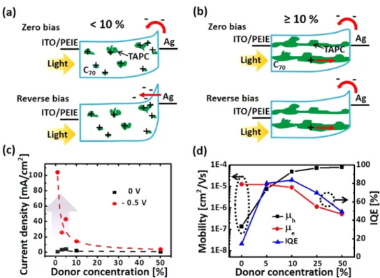
not the same as a general OSC structure. Figure 4a schematically illustrates the hole charge injection from the anode and the disconnected TAPC with donor concentration below 10%. Under illumination, the hole charges are trapped on isolated TAPC molecules, which builds an electricfield from
the BHJ toward the Ag electrode at the TAPC:C70/Ag interfaces; this occurs because the optical electricfield created by the incident light in the BHJ layer is positioned near the Ag electrode (Figure S12) and generates many trapped holes at the organic/metal interfaces.26,29 Then, the electron-injection barrier from Ag is narrowed because of the sharply curved energy band at the TAPC:C70 interfaces. Under reverse bias,
electron tunneling from Ag to C70 occurs despite the high electron-injection barrier from the anode to the lowest unoccupied molecular orbital of C70. Therefore, a higher EQE, above 100% (maximum 750%), was observed for TAPC concentrations 1, 3, and 5% under reverse bias (−0.5 V), as shown in Figure S13a. However, for more than 10% donor concentration, TAPC columnar hole pathways are formed, removing the trapped hole charges under illumination (Figure 4b). Hence, the electron tunneling disappears, reducing the EQE value to below 100%. Indeed, the current density calculated by EQE and photocurrent density from illuminated J−V under reverse bias (−0.5 V) sharply increases for donor concentration below 10%, as shown in Figures 4c and S13b, which illustrates that the TAPC molecules are disconnected and isolated at such low concentrations. The photovoltaic performance of the OSCs below 10% TAPC concentration is summarized inFigure S14 and Table S7, which demonstrate that the columnar TAPC leads to higher PCE.
Balance of e−h Mobility. Figure 4d andTable S1 show the e−h mobility and IQE with respect to the TAPC concentration. The hole mobility keeps decreasing with decreasing TAPC concentration below 50% because of the restricted hole-transport pathways. However, it should be noted that thefilm with 10% donor concentration still maintains 62% of the hole mobility of thefilm with 50% donor concentration owing to the preferentially columnar growth of TAPC, as revealed above. Moreover, the electron mobility dramatically increases with lower TAPC concentration, presumably because
Figure 4.Trap-assisted charge injection and correlation between e−h mobility and IQE. Schematic illustration of the energy diagrams of trap-assisted charge injection devices at zero and reverse bias (−0.5 V) for TAPC concentration (a) below 10% and (b) above 10%. (c) Current density under reverse bias and (d) e−h mobility and IQE as a function of TAPC concentration.
of the improved crystallinity of C70, as shown in Figure S3.21 Consequently, an improved e−h mobility balance for efficient charge collection was achieved at rather low donor concen-tration and the well-balanced mobility facilitated the reduction of charge recombination. Experimentally, the IQE of the low-donor-concentration OSCs outperformed that of the high-donor-concentration OSCs despite the reduction of exciton dissociation resulting from the lower number of TAPC/C70
interfaces (Figure S15).30,31However, for TAPC concentration below 10%, the severely reduced hole mobility due to the isolated TAPC islands deteriorated the IQE. Moreover, the decreased number of TAPC/C70interfaces at such low donor
concentrations can cause charge recombination and lower exciton dissociation.7,24
■
CONCLUSIONSTo summarize, we have proved that columnar structures are formed in low-donor-concentration BHJ layers. Experimentally, the preferentially columnar structure for hole transport at low donor concentrations was verified by the differences of the horizontal and vertical hole mobilities and was visualized by the potential profiles of samples with varying donor concentrations, obtained from KPFM analysis. The driving force of the columnar structures is the high interfacial tension between TAPC and C70, which results in self-assembled arrangements of
small molecules. However, below 10% donor concentration, the biased EQE showed trap-assisted charge injection, suggesting a disconnected arrangement of donor molecules. Finally, it was found that the OSCs exhibit maximum IQE at 10% TAPC concentration primarily because of the well-balanced e−h mobility.
■
EXPERIMENTAL SECTIONInverted OSC Fabrication. The OSCs were fabricated on 75 nm-thick ITO film-coated glass (JM International Co., Korea) substrates (sheet resistance: 20Ω/sq). Twice-sublimed 1,1-bis-(4-bis(4-methyl-phenyl)-amino-phenyl)-cyclohexane (TAPC, EM index Co., Korea) and fullerene (C70, 99.9%, EM
index Co., Korea) were used as the active materials of the OSCs. Prior to the evaporation of the materials, the precleaned substrates were treated in air plasma for 5 min. A 0.4 wt % PEIE solution, prepared by diluting polyethylenimine solution (Aldrich) with 2-methoxyethanol (Aldrich), was spin-coated onto the ITO substrates at 4000 rpm for 30 s and immediately annealed at 100 °C for 15 min. Next, the PEIE-coated ITO glasses were placed into a vacuum chamber (pressure < 3 × 10⁻⁷ Torr). The deposition of C70 (10 nm) at 0.5 Å/s was followed by that of TAPC:C70 (50 nm) onto the C70 layer.
Subsequently, MoO3 (10 nm) and Ag (150 nm) were deposited at 0.1 and 1.0 Å/s, respectively. The device area of all fabricated solar cells was 15 mm2.
Kelvin Probe Force Microscopy (KPFM). An Agilent 5500 atomic force microscope with a conductive noncontact cantilever coated with Pt/Ir was utilized for KPFM. The nominal resonance frequency, f0, used for mapping the topography was ∼75 kHz, and a 1 V to 10 kHz sinusoidal signal was additionally employed to measure the CPD. The frequency, which was far from f0 and much faster than the
topography feedback, prevented the cross-talk of the CPD with the topography mapping. The work function of the sample can be quantitatively evaluated by using the relationφsample=φtip− e× CPD.
Contact Angle. The water and glycerol contact angles of TAPC and C70 were measured by a contact angle analyzer
(Pheonix 150, SEO Inc.).
Electrical Characterization. The current density−voltage (J−V) curves were measured by a solar simulator under 100 mW/cm2 with an AM 1.5G filter (PEC-L12, Peccell Technologies). To calibrate the 1 sun, a crystalline silicon cell was used as the reference cell. The EQE was measured by a spectral measurement system (K3100 IQX, McScience Inc., Korea) with a 300 W Xe lamp, an optical chopper (MC 2000 Thorlabs), and a monochromator (Newport). The absorption of the OSCs was obtained from the reflectance, which was measured with an integrating sphere. Next, we calculated the total absorption of the device and the absorption of the active layer only using a transfer-matrix formalism.32 Therefore, refractive indices of each layer of OSCs including TAPC:C70
BHJ for 0, 5, 10, 25, and 50% were obtained by ellipsometry. To obtain realistic IQE, we multiplied the calibration factor (F_cal = measured total absorption/calculated total absorp-tion) by the calculated absorption of active layer only. Using these, IQE was estimated by dividing the measured EQE by the calculated absorption of active layer (e.g., TAPC and C70). For
reproducibility of device performance, five devices of TAPC:C70 OSCs were measured.
Photoluminescence (PL) Spectroscopy. Photolumines-cence (PL) of organic materials was measured by a PL spectroscopy system (LabRAM HR UV/Vis/NIR PL, Horiba Jobin Yvon, France). A He−Ne laser was used for excitation at a wavelength of 514 nm. Samples were prepared on glass substrates.
■
ASSOCIATED CONTENT*
S Supporting InformationThe Supporting Information is available free of charge on the ACS Publications websiteat DOI:10.1021/acsomega.7b01652. Extinction coefficients of TAPC and C70; transfer
process; EQE, IQE, and absorption of the inverted TAPC:C70 BHJ OSCs; TEM images of TAPC:C70;
current density−voltage (J−V) characteristics of the normal TAPC:C70 BHJ OSCs; photovoltaic
character-istics of the inverted ClAlPc:C70 and DBP:C70 BHJ OSCs; schematic illustration of the TAPC or C70added
TAPC:C70OSCs; absorption and dark current density of the inverted TAPC:C70BHJ OSCs with a TAPC or C70
layer; water and glycerol contact angles of TAPC and C70; schematic illustration of vertical and horizontal hole
transport in top surface of TAPC:C70 BHJfilm; vertical
potential profiles of TAPC:C70 BHJ layer; topographic
and CPD images of Si/TAPC:C70/Ag with 0 and 5%
TAPC obtained using KPFM measurements; horizontal potential profiles for 0 and 5% TAPC; optical electric field as a function of TAPC concentration; reverse-biased EQEs and illuminated J−V of trap-assisted charge injection devices; photovoltaic characteristics of the inverted TAPC:C70BHJ OSCs (PDF)
■
AUTHOR INFORMATIONCorresponding Author
*E-mail:[email protected]. ORCID
Eunji Lee:0000-0001-7494-1776
Jeong Young Park:0000-0002-8132-3076
Jung-Yong Lee:0000-0002-5347-8230 Present Address
#School of Electrical Engineering, Information & Electronics Research Institute, Korea Advanced Institute of Science and Technology (KAIST), 291 Daehak-ro, Yuseong-gu, Daejeon 34141, Republic of Korea (J.-W.S.).
Author Contributions
J.S. and J.L. conceived and designed the experiments and prepared the manuscript. J.S. and S.L. fabricated the OSC devices and performed measurements, such as those of the J−V characteristics, EQE, and absorption. M.K. fabricated and measured the organic thin-film transistor. S.J. measured the TEM and J.K. measured the KPFM. C.C. calculated the IQE. All authors discussed the results and commented on the manuscript.
Notes
The authors declare no competingfinancial interest.
■
ACKNOWLEDGMENTSThis work was supported by a National Research Foundation of Korea (NRF) grant funded by the Korea government (MSIP) (No. NRF-2015R1A2A2A01006689). We gratefully acknowl-edge the support from the Ministry of Trade, Industry & Energy (No. 20133030000130) and EEWS Climate Change Research Hub of KAIST (EEWS-2014-N01140052). KFPM measurement and CPD analysis are supported by IBS-R004-G4.
■
REFERENCES(1) Li, G.; Yao, Y.; Yang, H.; Shrotriya, V.; Yang, G.; Yang, Y. “Solvent Annealing” Effect in Polymer Solar Cells Based on Poly(3-Hexylthiophene) and Methanofullerenes. Adv. Funct. Mater. 2007, 17, 1636−1644.
(2) Veldman, D.; Ipek, O.; Meskers, S. C. J.; Sweelssen, J.; Koetse, M. M.; Veenstra, S. C.; Kroon, J. M.; van Bavel, S. S.; Loos, J.; Janssen, R. A. J. Compositional and Electric Field Dependence of the Dissociation of Charge Transfer Excitons in Alternating Polyfluorene Copolymer/ Fullerene Blends. J. Am. Chem. Soc. 2008, 130, 7721−7735.
(3) Sun, Y.; Welch, G. C.; Leong, W. L.; Takacs, C. J.; Bazan, G. C.; Heeger, A. J. Solution-Processed Small-Molecule Solar Cells with 6.7% Efficiency. Nat. Mater. 2012, 11, 44−48.
(4) Lee, S.-H.; Seo, J.-W.; Lee, J.-Y. Stable Inverted Small Molecular Organic Solar Cells Using a P-Doped Optical Spacer. Nanoscale 2015, 7, 157−165.
(5) Seo, J.-W.; Lee, S.-H.; Lee, J.-Y. Enhancing Quantum Efficiency of Parallel-Like Bulk Heterojunction Solar Cells. Appl. Phys. Lett. 2013, 103, No. 123301.
(6) Kim, Y.; Choulis, S. A.; Nelson, J.; Bradley, D. D. C.; Cook, S.; Durrant, J. R. Composition and Annealing Effects in Polythiophene/ Fullerene Solar Cells. J. Mater. Sci. 2005, 40, 1371−1376.
(7) Proctor, C. M.; Love, J. A.; Thuc-Quyen, N. Mobility Guidelines for High Fill Factor Solution-Processed Small Molecule Solar Cells. Adv. Mater. 2014, 26, 5957−5961.
(8) Zhang, M.; Wang, H.; Tian, H. K.; Geng, Y. H.; Tang, C. W. Bulk Heterojunction Photovoltaic Cells with Low Donor Concentration. Adv. Mater. 2011, 23, 4960−4964.
(9) Xiao, X.; Zimmerman, J. D.; Lassiter, B. E.; Bergemann, K. J.; Forrest, S. R. A Hybrid Planar-Mixed Tetraphenyldibenzoperiflan-thene/C-70 Photovoltaic Cell. Appl. Phys. Lett. 2013, 102, No. 073302. (10) Liu, S.-W.; Su, W.-C.; Lee, C.-C.; Cheng, C.-W.; Chou, C.-C.; Lin, C.-F. Absorbing Visible Light Materials of Subphthalocyanine and C-70 for Efficient Planar-Mixed Organic Photovoltaic Devices. J. Electrochem. Soc. 2013, 160, G14−G18.
(11) Jin, F.; Chu, B.; Li, W.; Su, Z.; Zhao, B.; Zhang, T.; Yan, X.; Gao, Y.; Wu, H.; Lee, C. S.; et al. The Influence of Donor Material on
Achieving High Photovoltaic Response for Organic Bulk Hetero-junction Cells with Small Ratio Donor Component. Org. Electron. 2013, 14, 1130−1135.
(12) Deibel, C.; Strobel, T.; Dyakonov, V. Role of the Charge Transfer State in Organic Donor-Acceptor Solar Cells. Adv. Mater. 2010, 22, 4097−4111.
(13) Zhuang, T.; Wang, X.-F.; Sano, T.; Hong, Z.; Li, G.; Yang, Y.; Kido, J. Fullerene C70 as a P-Type Donor in Organic Photovoltaic Cells. Appl. Phys. Lett. 2014, 105, No. 093301.
(14) Könenkamp, R.; Priebe, G.; Pietzak, B. Carrier Mobilities and Influence of Oxygen in C-60 Films. Phys. Rev. B 1999, 60, 11804− 11808.
(15) Strohriegl, P.; Grazulevicius, J. V. Charge-Transporting Molecular Glasses. Adv. Mater. 2002, 14, 1439−1452.
(16) Opitz, A.; Bronner, M.; Bruetting, W. Ambipolar Charge Carrier Transport in Mixed Organic Layers of Phthalocyanine and Fullerene. J. Appl. Phys. 2007, 101, No. 063709.
(17) Mishra, A.; Baeuerle, P. Small Molecule Organic Semi-conductors on the Move: Promises for Future Solar Energy Technology. Angew. Chem., Int. Ed. 2012, 51, 2020−2067.
(18) Böltau, M.; Walheim, S.; Mlynek, J.; Krausch, G.; Steiner, U. Surface-Induced Structure Formation of Polymer Blends on Patterned Substrates. Nature 1998, 391, 877−879.
(19) Zheng, Y.-q.; Potscavage, W. J., Jr.; Komino, T.; Hirade, M.; Adachi, J.; Adachi, C. Highly Efficient Bulk Heterojunction Photo-voltaic Cells Based on C-70 and Tetraphenyldibenzoperiflanthene. Appl. Phys. Lett. 2013, 102, No. 143304.
(20) Tress, W.; Petrich, A.; Hummert, M.; Hein, M.; Leo, K.; Riede, M. Imbalanced Mobilities Causing S-Shaped Iv Curves in Planar Heterojunction Organic Solar Cells. Appl. Phys. Lett. 2011, 98, No. 063301.
(21) Singh, T. B.; Sariciftci, N. S.; Yang, H.; Yang, L.; Plochberger, B.; Sitter, H. Correlation of Crystalline and Structural Properties of C-60 Thin Films Grown at Various Temperature with Charge Carrier Mobility. Appl. Phys. Lett. 2007, 90, No. 213512.
(22) Hau, S. K.; Yip, H.-L.; Acton, O.; Baek, N. S.; Ma, H.; Jen, A. K. Y. Interfacial Modification to Improve Inverted Polymer Solar Cells. J. Mater. Chem. 2008, 18, 5113−5119.
(23) Tress, W.; Merten, A.; Furno, M.; Hein, M.; Leo, K.; Riede, M. Correlation of Absorption Profile and Fill Factor in Organic Solar Cells: The Role of Mobility Imbalance. Adv. Energy Mater. 2013, 3, 631−638.
(24) Pandey, R.; Gunawan, A. A.; Mkhoyan, K. A.; Holmes, R. J. Efficient Organic Photovoltaic Cells Based on Nanocrystalline Mixtures of Boron Subphthalocyanine Chloride and C60. Adv. Funct. Mater. 2012, 22, 617−624.
(25) Kim, K.-H.; Kang, H.; Kim, H. J.; Kim, P. S.; Yoon, S. C.; Kim, B. J. Effects of Solubilizing Group Modification in Fullerene Bis-Adducts on Normal and Inverted Type Polymer Solar Cells. Chem. Mater. 2012, 24, 2373−2381.
(26) Katsume, T.; Hiramoto, M.; Yokoyama, M. Photocurrent Multiplication in Naphthalene Tetracarboxylic Anhydride Film at Room Temperature. Appl. Phys. Lett. 1996, 69, 3722−3724.
(27) Chen, H.-Y.; Lo, M. K. F.; Yang, G.; Monbouquette, H. G.; Yang, Y. Nanoparticle-Assisted High Photoconductive Gain in Composites of Polymer and Fullerene. Nat. Nanotechnol. 2008, 3, 543−547.
(28) Guo, F.; Yang, B.; Yuan, Y.; Xiao, Z.; Dong, Q.; Bi, Y.; Huang, J. A Nanocomposite Ultraviolet Photodetector Based on Interfacial Trap-Controlled Charge Injection. Nat. Nanotechnol. 2012, 7, 798− 802.
(29) Li, L.; Zhang, F.; Wang, J.; An, Q.; Sun, Q.; Wang, W.; Zhang, J.; Teng, F. Achieving Eqe of 16,700% in P3ht: Pc71bm Based Photodetectors by Trap-Assisted Photomultiplication. Sci. Rep. 2015, 5, No. 9181.
(30) Vandewal, K.; Widmer, J.; Heumueller, T.; Brabec, C. J.; McGehee, M. D.; Leo, K.; Riede, M.; Salleo, A. Increased Open-Circuit Voltage of Organic Solar Cells by Reduced Donor-Acceptor Interface Area. Adv. Mater. 2014, 26, 3839−3843.
(31) Credgington, D.; Durrant, J. R. Insights from Transient Optoelectronic Analyses on the Open-Circuit Voltage of Organic Solar Cells. J. Phys. Chem. Lett. 2012, 3, 1465−1478.
(32) Pettersson, L. A. A.; Roman, L. S.; Inganas, O. Modeling Photocurrent Action Spectra of Photovoltaic Devices Based on Organic Thin Films. J. Appl. Phys. 1999, 86, 487−496.