한 국 방 재 학 회 논 문 집 제11권 3호 2011년 6월
pp. 83 ~ 89
소방방재
Full Scale Testing of the Effect of Stairwell Pressurization on
Pressure Differential and Flow Velocity
Son, Bong-Sae* · Park, Kyung-Hwan** · Chang, Young-Bae***
···
Abstract
A series of full-scale testing was conducted to examine the effect of stairwell pressurization on the pressure differential between the stairwell and the auxiliary room and between the auxiliary room and the residence. Also, flow velocity profiles at open doors were measured. The building tested was a condominium that had twenty floors above the ground and two floors underground. For pressurization of the stairs, a blower was used to supply air into the stairwell at one location underground. Thirteen different cases were tested, and test variables included the number of floors with open doors and the flow rate of the air supply. When the doors on the first floor were open, the pressure differential between the stairwell and the auxiliary room was distributed almost uni-formly except for locations near the first floor. When the flow rate was in the range of 180~270 CMM and the doors of one floor were open, the flow velocity could satisfy the requirement of fire safety standards and the stairwell pressure was positive at all lev-els. However, the minimum pressure requirement (10 Pa) could not always be satisfied. When doors on two floors were open, the flow velocity requirement could be satisfied by increasing the flow rate, but it was found impractical to satisfy the minimum pres-sure requirement without causing excessive prespres-sure differential in the area near the blower.
Key words : Smoke control, Stairwell pressurization, Critical velocity, Pressure differential, Over pressure
요
지
계단실을 직접 가압했을 경우에 계단실과 부속실 사이의 차압 및 부속실과 세대 사이의 차압이 어떤 영향을 받는지 연구하 기 위해 실건물을 사용해 실험했다. 또한 열린문에서의 유속분포도 측정하였다. 본 연구에 사용된 건물은 지상 20층 지하 2층 의 공동주택이다. 계단실을 가압하기 위해서 송풍기를 지하 1층에 설치하여 외부공기를 계단실로 공급했다. 13가지 경우에 대 한 실험을 실시했으면 주 실험변수들은 문이 개방된 층의 숫자와 위치 및 송풍량이었다. 지상 1층 문들만이 열린 상태에서는 계단실과 부속실 사이의 차압 및 부속실과 세대 사이의 차압이, 1층 부근을 제외하고는, 비교적 균일하게 분포되었다. 실험결과 180~270 CMM에서 한 층이 개방되어도 화재안전기준의 방연풍속을 만족하였고, 계단실은 전체적으로 양압을 유지할 수 있었 으나 최소차압 조건(10 Pa)을 항상 만족시키지는 못하였다. 두 층의 문들이 개방된 경우, 유량을 증가함으로써 최소유속조건은 만족시킬 수 있었으나 가압지점 인근에서 과압이 발생하지 않는 상태에서 최소차압조건을 만족시키는 것은 비현실적임을 발견 했다. 핵심용어 : 제연, 계단실 가압, 방연 풍속, 차압, 과압 ···1. Introduction
In the United States, approximately 75 percent of the fire victims were killed by smoke (Beitel, 2000). Methods of containing smoke by pressuring the stairwell, which is used for escaping, have been extensively studied since the 1970’s by researchers in North America including Tamura and Klote (Tamura and Klote, 1987; Klote, 1988). In Korea, pressurization of the auxiliary room was addressed in the appendix of “Technical Standard for Installation of Escape
Stairs in Special Buildings and Smoke Control Facility for Use of Emergency Elevators” which became effective in 1995. The year of 2004 saw the development of a new stan-dard “Fire Safety Stanstan-dard for Special Escape Stairwell and Smoke Control Facility in the Auxiliary Room” which allowed the pressurization of only stairwell or both stairwell and auxiliary rooms. However, the development of design methods and standards for stairwell pressurization is not mature yet, and it is a common practice to pressurize only auxiliary rooms. Such methods are known to have problems ***Member·Department of Fire & Disaster Protection Engineering, Kyungwon University, S. Korea (E-mail : bsson@kyungwon.ac.kr)(Corresponding author) ***Department of Disaster Science, University of Seoul, S. Korea
including:
(1) The air pressure in the auxiliary room can become excessively high making it too difficult to open the door.
(2) In cases where the interior surfaces are finished with stone, the required pressure differential may not be developed because of the gaps between stones and between the stone and the door (Kim, 2010).
(3) When the escape door is opened it can be difficult to generate the required critical flow velocity for smoke control (Kim, 1992).
Because of various reasons including those listed above, many researchers have tested the effects of pressurizing the stairwell as well as the auxiliary rooms (Tamura, 1992). It is recommended not to use the method of pressurizing only the auxiliary rooms (EN12101-6, 2005). Miller and Beasley (2009) suggests that stairwell pressurization is a viable means of smoke control when used without pressurizing the elevator shaft and that it is very difficult to achieve the same purpose by pressurization of the elevator shaft. Bowers and others (2010) conclude that it is impossible to satisfy the requirements for pressurization of elevator shafts in the cur-rent International Building Code. Ferreira (2008) suggests to provide air supply inlets every 3~5 floors to evenly distrib-ute air throughout the stair.
The purpose of this study is to examine the possibility of pressurizing the stairwell to obtain adequate pressure differ-ential and flow velocity as required in the “Fire Safety Stan-dard for Special Escape Stairwell and Smoke Control Facility in the Auxiliary Room” and to evaluate the feasibil-ity of applying the method of stairwell pressurization to real-world design of tall buildings.
2. Method of Experiment
2.1 The building
The building tested was a condominium that had twenty stories above the ground level and two stories underground. Every floor, excluding the first floor, had an auxiliary room between the stairwell and the residence. The auxiliary room was for the emergency evacuation elevator. The stairwell had a landing for each floor, which is a common design. Pressurization of the stairwell was done by blowing air into the basement (first floor underground).
2.2 Equipment
A centrifugal blower (27 CMM at 3 kPa, Fig. 1a) was used for high pressure testing, and an axial fan (450 CMM at 300 Pa, Fig. 1b) was used for low-pressure, high-flow air supply. For measurement of flow rate and flow velocity pro-file we used Tae-heung Airtron Flow and KAIJO wa590, respectively. The centrifugal blower was used for the case
where all doors were closed, and the axial fan was used for all other cases where doors on one or two floors were open. Pressure differential was measured on every other floor (even numbered) above the ground and the first under-ground floor, ten locations above the under-ground and one loca-tion underground. On those floors, doors between the stairwell and the auxiliary room and between the auxiliary room and the residence were instrumented with differential pressure taps. At each open door, the flow velocity was measured at 64 locations (8 × 8 grid points) or 40 locations (5 × 8 points).
2.3 Testing scenarios
Scenario #1: It was assumed that sensors detected fire activating smoke control devices. All doors remained closed (T02 in Table 1). Pressure differential and the effective leak area were determined through this testing.
Scenario #2: It was assumed that warning buzzers have been activated, and people evacuated from the residential area into the stairwell through the auxiliary room. Doors to the residence and to the stairwell were opened at the same time. The purpose was to examine whether a sufficient air
Fig. 1. Air supply fans
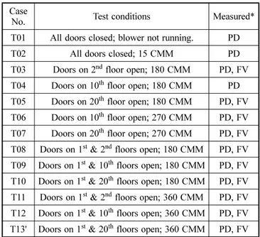
Table 1. Test conditions Case
No. Test conditions Measured*
T01 All doors closed; blower not running. PD
T02 All doors closed; 15 CMM PD
T03 Doors on 2nd floor open; 180 CMM PD, FV
T04 Doors on 10th floor open; 180 CMM PD
T05 Doors on 20th floor open; 180 CMM PD, FV
T06 Doors on 10th floor open; 270 CMM PD, FV
T07 Doors on 20th floor open; 270 CMM PD, FV
T08 Doors on 1st & 2nd floors open; 180 CMM PD, FV T09 Doors on 1st & 10th floors open; 180 CMM PD, FV T10 Doors on 1st & 20th floors open; 180 CMM PD, FV T11 Doors on 1st & 2nd floors open; 360 CMM PD, FV T12 Doors on 1st & 10th floors open; 360 CMM PD, FV T13' Doors on 1st & 20th floors open; 360 CMM PD, FV *PD: Pressure differential; FV: Flow velocity
flow velocity (critical velocity) could be obtained to prevent the smoke from entering the stairwell. Two different flow rates were selected for testing: 180 CMM for cases T03~T05 and 270 CMM for T06~T07 (Table 1).
Scenario #3: If there are several people who need to be evacuated from the fire floor, it is possible that people can enter the refuge floor while others leave the fire floor. Also for the purpose of firefighting, the doors of the refuge floor may need to stay open while people continue evacuating. Cases T08~T10 are with 180 CMM of air supply, and T11~T13 are with 360 CMM (Table 1).
3. Test results and discussion
3.1 T01-T02: All doors closed
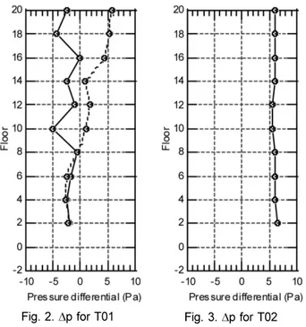
When all doors were closed without a fan running, the pressure in the stairwell was lower than that in the auxiliary room on every floor (Fig. 2). On all floors above the ninth floor, the air pressure in the auxiliary room was higher than that of the residence, and the largest difference (5.8 Pa) was observed on the highest floor. Below the ninth floor, the pressure differential between the auxiliary room and the res-idence was negative, and the largest difference was observed on the fourth floor (2.2 Pa). On all floors, the stairwell pres-sure was lower than or nearly the same as the auxiliary room pressure. In general, below the ninth floor, the residence had the highest pressure and the stairwell had the lowest pressure, but the differences were not significant. On floors above the ninth, the auxiliary room had the highest pressure.
It is likely that the nearly linear curve of the pressure dif-ferential between the auxiliary room and the residence, which crosses the neutral point at the ninth floor, represents
the pattern of pressure profile in the elevator shaft. The pat-tern of pressure differential between the stairwell and the auxiliary room implies that the air flows from the auxiliary room to the stairs.
When the air supply fan was turned on, the pressure dif-ferential between stairwell and the auxiliary room became positive on all levels and its magnitude was nearly constant ranging from 5.5 to 6.5 Pa (Fig. 3). (Note: In Fig. 3, the dif-ferential pressure between the auxiliary room and the resi-dence is not available.) The test result indicates that it is possible to generate a uniform pressure distribution even with only a single blower installed at a lower part of the building. Based on the equation below, the effective leakage area is found to be 0.006 m2, which is nearly half of the allowable limit (0.1 m2):
(1) where
K: Constant, 0.825
A: Effective area of leakage [m2] p: Pressure differential [Pa] Q: Leakage [CMM]
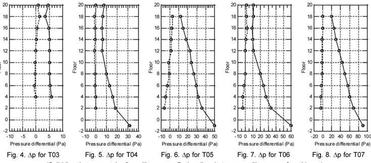
3.2 T03-T07: Doors on fire floor open – Pressure differential
When it was assumed that the second floor was the fire floor, the air pressure in the stairwell was higher than that in the auxiliary rooms by 3.3~5.7 Pa, but the pressure dif-ferential between the auxiliary room and the residence was much lower, ranging from -0.5 to 1.3 Pa (T03, Fig. 4). Even though pressurization of the stairwell did not generate high pressure differential between the auxiliary room and the res-idence, it significantly reduced the variation of pressure dif-ferential observed in case T01.
When it was assumed that the tenth floor caught fire, the pressure differential between stairs and the auxiliary rooms was in the range of 6~32 Pa (T04, Fig. 5). It was observed, however, that the auxiliary rooms were at lower pressure compared to the residence. It indicates that the air leaking from the stairs to the auxiliary room was not sufficient for pressurization of the auxiliary room.
When the twentieth floor doors were open, the pressure differential between the stairs and the auxiliary room remained positive, ranging from 12 to 50 Pa (T05, Fig. 6). The pressure differential between the auxiliary room and the residence was negative on several floors. It is seen that the pressure drop due to the aerodynamic friction in the stair-well is approximately 2 Pa per floor. This information can be useful for calculation of the static pressure requirement of a fan for effective smoke control.
When the doors on the tenth floor were open with the
Q=KA p
Fig. 2. ∆p for T01 Fig. 3. ∆p for T02
(Solid line: between stairs & auxiliary room; Broken line: between auxiliary room & residence)
supply air flow increased from 180 CMM to 270 CMM, the pressure differential between the stairs and the auxiliary room was increased to 8.8~60 Pa (T06, Fig. 7). The increased flow rate resulted in the elevation of the pressure differential on all floors, and on low level floors the pres-sure differential became excessively high. When the doors on the twentieth floor (instead of the tenth) were open, pres-sure differential between the stairs and the auxiliary room became 19~90 Pa, and the pressure drop due to vertical air flow in the stairwell also increased to approximately 3.7 Pa per floor (T07, Fig. 8).
It was shown that the stairwell could be pressurized with a single blower even when doors at one floor were open. However, it was impossible to satisfy the minimum pressure requirement (10 Pa) on every floor without over-pressuriz-ing the area near the blower. Also, pressurizover-pressuriz-ing only the stairwell did not generate adequate level of pressure in the auxiliary rooms, probably because of the vertical air flow through the elevator shaft.
3.3 T03-T07: Doors on fire floor open – Flow velocity The flow velocity profile was measured at the open door
Fig. 4. ∆p for T03 Fig. 5. ∆p for T04 Fig. 6. ∆p for T05 Fig. 7. ∆p for T06 Fig. 8. ∆p for T07 (Solid line: between stairs & auxiliary room; Broken line: between auxiliary room & residence)
Table 2. Flow velocity on 2nd floor (T03)* Table 3. Flow velocity on 20th floor (T05)*
Table 4. Flow velocity on 10th floor (T06)* Table 5. Flow velocity on 20th floor (T07)*
between the auxiliary room and the residence on the fire floor. Note that the door to the stairs also was open on the fire floor. When the doors on the second floor were open with the flow rate of 180 CMM, the average flow velocity at the door to the residence was 1.8 m/s, the highest velocity was 2.5 m/s, while the lowest was 0.9 m/s (T03, Table 2). When the fire floor was changed to the twentieth floor, they became 1.7 m/s, 2.5 m/s, and 0.3 m/s, respectively (T05, Table 3). It is shown that, for the same flow rate of air sup-ply, the average flow velocity tended to decrease with the distance from the blower, while the flow velocity profile became more non-uniform.
The effect of increased flow rate is shown in Tables 4 and 5 (T06 and T07). For the case where the tenth floor was the fire floor with the flow rate of 270 CMM, the average flow velocity was 2.3 m/s, and the extreme values were 3.5 and 0.6 m/s (T06, Table 4). It is also shown that the air velocity is lower near the door frame than near the center of the opening. When the twentieth floor was the fire floor, the air flowing into the residence was increased with the average velocity of 2.4 m/s and the extremes of 3.6 m/s and 0.9 m/ s (T07, Table 5). It is believed that the air velocity was higher on the twentieth floor compared to that on the tenth floor mainly because of the influx of air from the residence to the auxiliary rooms on low-level floors, which moves upward through the elevator shaft.
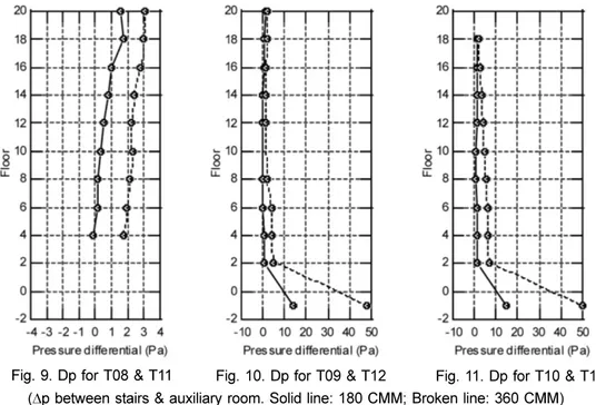
3.4 T08-T13: Doors on fire floor and refuge floor open – Pressure differential
When the doors on the first and second floors were open, the pressure differential between the stairs and the auxiliary rooms were within the range of -0.1~1.7 Pa at 180 CMM, but it increased to 1.7~3.1 Pa when the flow rate doubled (T08 & T11, Fig. 9). When the doors on the first and tenth
floors were open, the pressure differential appeared to be the lowest near the tenth floor (T09 & T10, Fig. 10). It is inter-esting that even when the fire floor was switched from the tenth floor to the twentieth floor, the lowest pressure occurred on the tenth floor again at 180 CMM (Figs. 10 & 11). When the flow rate doubled (360 CMM), however, the pressure differential monotonically decreased with elevation until it became the minimum on the twentieth floor (T10 & T13, Fig. 11). In general, when doors on two floors were open at the same time, a large portion of the air leaked through the doors on the first floor (refuge floor), but the stairs could still be pressurized when the flow rate was large enough.
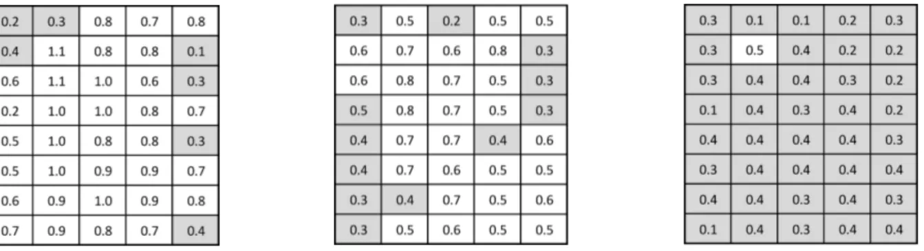
3.5 T08-T13: Doors on fire floor and refuge floor open – Flow velocity
The flow velocity profile was measured at the open door to the residence on the fire floor, which was assumed to be the second, tenth, or twentieth floor. Doors on the first floor (refuge floor) remained open throughout the testing for T08~T13. The air velocity profile on the second floor at 180 CMM (T08) is shown in Table 6. Near the center of the opening, the flow profile is almost uniform and the mini-mum velocity requirement (critical flow velocity, 0.5 m/s) was satisfied. There were spots near the door frame, how-ever, where the flow velocity was less than the requirement. When the tenth floor became the fire floor (T09), the shape of the flow velocity profile was similar to that for the previous case (T08), but the average flow velocity was reduced from 0.7 m/s to 0.5 m/s (Table 7). When the doors on the twentieth floor were open (T10), almost in the entire section of the opening the air flow could not reach the required velocity (Table 8). However, the effect of increased air supply is clearly seen in Tables 9~11, where the number
Fig. 9. Dp for T08 & T11 Fig. 10. Dp for T09 & T12 Fig. 11. Dp for T10 & T13 (∆p between stairs & auxiliary room. Solid line: 180 CMM; Broken line: 360 CMM)
of sections where the flow velocity was less than the critical value significantly decreased by doubling the flow rate. The effect of increased flow rate appears especially dramatic when Table 11 (T13) is compared with Table 8 (T10).
This series of testing demonstrated that the flow velocity near the door frame tends to be lower than that in the cen-tral section of an open door, the average flow velocity increases with the supply flow rate, and the farther the fire floor from the blower the lower the average flow velocity on that floor.
4. Conclusions
1) When all the doors were closed (Scenario #1) and the air was supplied at 15 CMM, the air pressure in the stairwell was higher than that in the auxiliary room by 6 Pa on average.
2) When all the doors on the fire floor were open (Sce-nario #2) and the air leaked from the stairwell, stair-well pressure could always be maintained higher than that of the auxiliary room. With 180 CMM of air sup-ply, the pressure differential could not satisfy the required value of 10 Pa (EN12101-6) except for the case the fire floor was the twentieth floor. The mini-mum pressure requirement could be satisfied by increasing the air flow rate, but at the cost of excessive pressure differential near the blower.
3) When the doors only on the fire floor were open with 180 CMM of air supply, the average flow velocity at the door to the residence was 1.8 m/s on the second
floor and 1.7 m/s on the twentieth floor. When the air supply was 270 CMM the flow velocity at the residence door became 2.3 m/s on the tenth floor and 2.4 m/s on the twentieth floor. These results satisfy the anti-smoke critical flow velocity requirement in the fire safety standards. The flow velocity requirement of 2.0 m/s on stairs for fire fighters (EN12101-6) could be satisfied only with 270 CMM of air supply.
4) When the doors on both the fire floor and the refuge floor were open (Scenario #3), the stairwell could still maintain a higher pressure than the auxiliary room, though the difference was small. Most of the supply air leaked out through the refuge floor (first floor) and the location of the fire floor had little effect on the differ-ential pressure. The minimum pressure requirement could not be satisfied even with 360 CMM of air sup-ply.
5) When the supply flow rate was 180 CMM, the average flow velocity at the open door to the residence became 0.7 m/s on the second floor and 0.5 m/s on the tenth floor, satisfying the requirement (0.5 m/s). However, on the twentieth floor the average velocity was only 0.3 m/s, failing to satisfy the requirement. When the supply flow rate was increased to 360 CMM, the average flow velocity at the door to the residence satisfied the requirement with 1.4 m/s on the second floor, 1.0 m/s on the tenth floor, and 0.78 m/s on the twentieth floor. However, the flow velocity requirement was not satis-fied at some corners of the opening.
In summary, when the escape stairwell for a twenty-story
Table 6. Flow velocity on 2nd floor (T08)* Table 7. Flow velocity on 10th floor (T09)* Table 8. Flow velocity on 20th floor (T10)*
Table 9. Flow velocity on 2nd floor (T11)* Table 10. Flow velocity on 10th floor (T12)* Table 11. Flow velocity on 20th floor (T13)*
building was pressurized by a 180 CMM fan with doors on one floor open, flow velocity on the fire floor was high enough, but the minimum pressure requirement could not always be satisfied without causing an excessive pressure near the blower. When doors on two floors were open, it requires a higher rate of air flow to satisfy the flow velocity requirement but it appears impractical to satisfy the mini-mum pressure requirement without causing an excessive pressure differential near the blower.
Acknowledgments
This work was supported by the Kyungwon University Research Fund of 2011 (KWU-2011-R090).
References
Beitel, J.J., Wakelin, A.J. and Beyler, C.L. (2000) Analysis of smoke movement in a building via elevator shafts, Report for Smoke Safety Council, Beaverton, OR.
Bowsers, D.C., Ellision, J.R., Beasley, D.E. and Miller, R.S. (2010) Numerical Study of Elevator and Stairwell Pressurization Sys-tems Using detailed building models, 8th International Confer-ence on Performance-Based Codes and Fire Safety Design Methods, Society of Fire Protection Engineers, Lund, Sweden.
Ferreira, M.J. and Cutonilli, J. (2008) Protecting the stair enclosure in tall buildings impacted by stack effect, CTBHU (Council on Tall Buildings and Urban Habitat) 8th World Congress, Dubai. Kim, J.S (2010) Method of stack effect in high-rise building,
Profes-sional Engineer Conference, Seoul, Korea.
Kim, J.H (1992) Heat Transfer, 4th ed., McGraw-Hill, New York, pp. 333-351.
Klote, J.H. (1988) An analysis of the influence of piston effect on elevator smoke control, NBSIR 88-3751, Gaitherburg, MD, National Bureau of Standards.
Miller, R.S. and Beasley, D. (2009) On smoke control by pressuriza-tion in stairwell and elevator shafts, Building and Environment, Vol. 44, pp. 1306-1317.
Tamura, G.T. and Klote, J.H. (1987) Experimental fire tower studies on elevator pressurization systems for smoke control, ASHRAE Transaction, Vol. 93, pp. 2235-2257.
Tamura, G.T. (1992) Assessment of stair pressurization systems for smoke control, NRCC.
EN12101-6 (2005) Smoke and heat control systems part 6-specifica-tion for pressure difference systems-kits.
National Emergency Management Agency (2010) Code of smoke control system at stair and emergency lifts.
◎ 논문접수일 : 10년 12월 09일 ◎ 심사의뢰일 : 10년 12월 20일 ◎ 심사완료일 : 11년 04월 27일