845
-Abstract — A suspending force control based on fuzzy logic control is proposed to apply on a novel hybrid bearingless switched reluctance motor(BLSRM) which has separated torque and suspending force pole. Due to the unique structure, the suspending force control system can be easily decoupled from torque control system. In this paper, two fuzzy controller targeted at x-axis direction and y-axis direction are adopted to maintain the shaft at center position, which is very necessary for stable operation of BLSRM. By replacing the traditional PI block with modified fuzzy logic controller, the suspending system can behave a good performance, and the proposed scheme can be verified by simulation results.Index Terms—bearingless switched reluctance motor, suspending force control, fuzzy logic controller
1.INTRODUCTION
Switched-reluctance motors(SRMs) have substantial benefits in many applications. Their particular characteristics are simple construction, low cost, fault tolerance, high efficiency, and the ability to operate in a high-temperature environment. However, mechanical bearing limits SRMs’ high speed ability. Bearingless switched reluctance motors (BLSRMs) can avoid the contact and the lubrication between motor shaft and bearing, and they can generate radial forces to levitate the rotor by changing the flux density in the motor air gap[1]-[3]. Thus, BLSRMs have an advantage in high-speed and super high speed starters/generators .
Moreover, due to mechanical errors, there is unbalanced air gap between the stator and rotor. It causes large magnetic attraction force and is one of the causes of vibration that have come into problems in SRM. Take Fig. 1 as an example, where the large circle and small circle in solid represent motor stator and rotor, respectively. As the rotor eccentricity makes air gap 1 smaller than the average gap, and makes air gap 2 larger than the average gap; therefore, the radial force between air gap 1 is greater than the radial force between air gap 2. The rotor has the tendency of running to the left, while the stator has the tendency of running to the right. If adopting the mechanical bearing in support, the rotor has greater damping, and its running tendency is not the real action due to the solid steel structure. However, the stator might run to the right, as shown in broken line in Fig. 1. Moreover, once there is running operation, the result is that the eccentricity is further worsened, thus causing serious eccentric vibration.
<Fig. 1> Simplified model to show vibration control effect in BSRM
Recently, several structures of BLSRM have been proposed [4-6]. But all of them are based on general SRM structure, so the torque control is coupled with the suspending force control. A BLSRM with
hybrid stator poles is proposed [7]. Compared with conventional BLSRM, the suspending force performance is improved and the air-gap is easier to control, but in this structure only half of the stator poles are used for the torque, output power density is very low. Moreover, in the motor long flux paths are present and flux reversal exists in the stator core, which increases the magneto motive force (MMF) requirements and leads to higher core losses. Furthermore, the effect of torque current on the suspending force is very large when the torque and suspending force windings are excited simultaneously.
The torque production in SRM drive is highly nonlinear due to the dependency of the machine torque on rotor position and phase current. Several methodshave been reported in the literature for fault-tolerant SRM drive. Current profiling and extended conduction of the healthy phases are few amongst those methods. Most of these methods use offline data collected from the machine during static conditions, which does not incorporate any dynamic changes in the machine parameters. Furthermore, most methods are limited to speeds well below the base speed of the motor and are not capable of delivering torque with minimized ripple during fault conditions.
In order to improve the performances of BLSRM, a novel 12/14 hybrid stator pole type BLSRM is proposed [8]. The proposed structure has separated torque and suspending force poles, so the torque control can be decoupled from the suspending force control. Moreover, due to the short flux path without any reversal flux in the stator core, compared to the 8/10 hybrid stator pole type BLSRM, the output torque is significantly improved and the air-gap is easier to control. In order to verify the proposed structure, according to the torque control decoupled from suspending force control in the novel structure, this paper proposed a control scheme.
In the proposed control scheme, a simple PI controller is used to regulate the speed of the proposed BLSRM, and two fuzzy logic controller are used to generate the desired suspending force commands to keep the rotor in the center position. The validity of control scheme are verified by the simulation results.
2.The NOVEL 12/14 HYBRID STATOR POLE TYPE BLSRM 2.1 Structure and Operate Principle of Target BLSRM
<Fig. 2> Basic structure of the proposed BLSRM
퍼지 논리 제어기를 사용한 축방향지지력 제어
하잉걸*, Fengge Zhang*, 안진우**
심양공업대*, 경성대**
Suspending Force Control of 12/14 BLSRM Using Fuzzy Logic Controller
Yingjie He*, Fengge Zhang*, Jin-Woo Ahn**
Shenyang University of Technology*,Kyungsung University**
846
-A novel 12/14 hybrid stator pole type BLSRM with short flux paths and no flux-reversal in the stator is proposed in Fig.2.The new structure has separated torque and suspending force poles. Windings on the torque poles PA1, PA2, PA3 and PA4 are connected in series to construct phase A, and windings on the torque poles PB1, PB2, PB3 and PB4 are connected in series to construct phase B. The x-direction suspending force is generated by currents flowed in the suspending force poles Pxp and Pxn. Such as, the current ixp in the stator pole Pxp generates positive xdirection suspending force, and the current ixn in the stator pole Pxn can generate the negative x-direction suspending force. Similarly, the suspending forces for the y-direction can be generated by the currents iyp and iyn which flow in suspending force poles Pyp and Pyn, respectively. Meanwhile, in order to get the continuous suspending force, the suspending force pole arc is selected not to be less than one-rotor pole pitch.
Because of independent characteristics between torque and suspending force poles, the produced suspending force has excellent linearity according to rotor position and independent characteristics of the torque if compared with the conventional BLSRM. Therefore, torque control can be decoupled from the suspending force control. Due to the short flux path without any reversal flux in the stator core, compared to 8/10 hybrid stator pole type BLSRM, the output torque is significantly improved and the air-gap is easier to control. 2.2 Magnetic Flux Distribution
Fig. 3.shows magnetic flux distributions of the 12/14 BLSRM. As shown in the figure, when the motor rotates, the flux path of the 12/14 type is short and there is no flux reversal in the stator core. This will decrease the MMF requirements and lead to lower core losses.
(a) Phase A and Pyp are excited
(b) Phase A and Pxn are excited
<Fig. 3> Magnetic flux distributions of the proposed 12/14 type
2.1 Suspending Force Characteristics
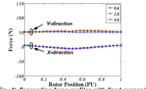
The suspending force profiles with fixed suspending force current 2A and various torque currents are shown in Fig. 4. As seen in the
figure, the effect of torque current on the suspending force is small enough to be ignored when compared to the suspending force generated by the suspending force winding.
<Fig. 4> Suspending force profiles with fixed suspending force current 2A and various torque currents 3. CONTROL SCHEME OF THE NOVEL BLSRM In order to verify the proposed BLSRM, based on the torque control decoupled from the suspending force control in the novel structure, a control scheme for the proposed BLSRM is proposed in Fig. 5. As shown in the figure, a PI type speed controller is adopted to regulate the motor speed. Two fuzzy logic controller, one for x-direction and the other for y-direction, are used to generate the desired suspending force commands Fx* and Fy* as shown in the following equation to keep the rotor at the center position. The above control algorithms are realized by a Texas Instruments (TI) TMS320F28335 digital signal processor (DSP).
<Fig. 5> Control scheme of the proposed BLSRM A fuzzy controller based on the offline knowledge of the machine characteristics would not be different from a conventional controller using lookup tables or offline stored machine characteristics.
In modern fuzzy control schemes, the knowledge base can be obtained through adaptive methods, which makes the controller robust toward any changes in machine characteristics and operating conditions. Therefore, adaptive fuzzy control is one of the appropriate schemes for controlling SRM drives [9]. Fig. 6. shows the block diagram of the adaptive fuzzy controllerfor SRM drives.
<Fig. 6> Block diagram of the adaptive fuzzy controller. The rotor position in each electrical cycle is used as the input variable and the desired/commanded phase current is the output variable of the fuzzy controller. The fuzzy membership function for the phase angle is composed of five triangular functions in the
847
-motoring and one rectangular function in the generating regions.if and
(1)
where is
the error and
is the weight of the singleton of output variable corresponding to the rule. In this paper, only the motoring operation is considered. The max-product rule of inference scheme is used and the output is determined using the center of average for defuzzification as
(2)where denotes the membership function of the fuzzy set of
input variable of and is the normalized activation function for
each fuzzy rule.
In the event of fault, the membership functions adapts in such a way that it maximizes the conduction period with increased peak current to compensate for the torque lost by the faulty phases.
4. SIMULATION RESULTS
Figs. 7. show the simulation results of the suspending force control. From the figures, it can be seen that, when the suspending force control is applied, the rotor moves to its balanced position.
<Fig. 7> Bimulation results of the suspending force control Figs. 8. and 9. show the simulation results of displacement, commend force and real force of X-axis and Y-axis respectively of the BLSRM. From the figures, it can be seen that, when the suspending force control is applied, the rotor moves to its balanced position immediately. And the response of the real force follow the commend force is very good.
<Fig. 8> The displacement, commend force and real force of X-axis
<Fig. 9> The displacement ,commend force and real force of Y-axis
5. CONCLUSIONS
The suspending force control based on fuzzy logic controller has been applied on a 12 /14 hybrid BLSRM. The simulation results show good performance of the proposed scheme, and more experiments which can show the scheme reliability are needed to be done in further research.
REFERENCES
[1] T. Higuchi, H. Kawakatsu, and T. Iwasawa, “A study on magnetic suspension of switched reluctance motor,” (in Japanese) in Proc. Conf. Rec.IEEJ Annu. Meeting, Tokyo, Japan, 1989, pp. 6-122–6-123.
[2] J. Bichsel, “The bearingless electrical machine,” in Proc. Int. Symp. Magn. Suspension Technol., NASA Langley Res. Center, Hampton, 1991, pp. 561–573.
[3] T. Fukao, “The evolution of motor drive technologies. Development of bearingless motors,” in Proc. 3rd Power Electron. Motion Control Conf. (IPEMC), Beijing, China, 2000, vol. 1, pp. 33 –38.
[4] Feng-Chieh Lin and Sheng-Ming Yang, “An Approach to Producing Controlled Radial Force in a Switched Reluctance Motor”, IEEE Trans. Ind. Electron., vol. 54, no.4, pp.2137-2146, 2007.
[5] Li Chen and Wilfried Hofmann, “Analytically Computing Winding Currents to Generate Torque and Levitation Force of a New Bearingless Switched Reluctance Motor”, in Proc.12th EPE-PEMC, Aug. 2006, pp.1058-1063.
[6] Carlos R. Morrison, Mark. Siebert and Eric Ho, "Electromagnetic Forces in a Hybrid Magnetic-Bearing Switched-Reluctance Motor", IEEE Trans. on Magnetics, vol.44, no.12, December 2008. [7] H. J. Wang, D. H. Lee, and J. W. Ahn, "Novel Bearingless
Switched Reluctance Motor with Hybrid Stator Poles: Concept, Analysis, Design and Experimental Verification," Proc. of 11th Int. Conf. on Electrical Machines and Systems (ICEMS 2008), Wuhan (China), October 2008, pp.3358-3363.
[8] Zhenyao Xu, Dong-Hee Lee, Fengge Zhang, and Jin-Woo Ahn., “Hybrid Pole Type Bearingless Switched Reluctance Motor with Short Flux Path”, Proc. of 14th Int. Conf. on Electrical Machines and Systems (ICEMS 2011), Beijing (China), August 2011. [9] S. Mir, M. Elbuluk, and I. Husain, “Torque-ripple minimization in
switched reluctance motors using adaptive fuzzy control,” IEEE Trans. Ind. Applicat., vol. 35, pp. 461–468, Mar./Apr. 1999.