Overall Instrumentations for the ATLAS Integral Effect Test Program
B.J.Yun, K.H.Kang, B.D.Kim,W.P.Baek
Korea Atomic Energy Research Institute, P.O.Box 105, Yuseong, Daejeon, 305-600, KOREA, bjyun@kaeri.re.kr
1. Introduction
Korea Atomic Energy Research Institute (KAERI) is constructing a thermal-hydraulic integral effect test (IET) loop, the ATLAS(Advanced Thermal-hydraulic Test Loop for Accident Simulation)[1]. The ATLAS test facility is basically designed according to the three-level scaling methodology of Ishii et al.[2]. The test facility has the following characteristics: (a) a 1/2-height, 1/288-volume, and full-pressure simulation of the APR1400, (b) geometrical similarity with the
APR1400 including 2 (hot legs)
×
4 (cold legs) reactorcoolant loops, a direct vessel injection(DVI), an integrated annular downcomer, etc.,(c)incorporation of the specific design character istics of the 1,000 MWe-class KSNP such as a cold leg injection(CLI) and the low-pressure injection pumps, (d) a maximum 8% of the scaled nominal core power, (d) simulation capability of broad scenarios, including the reflood phase of the large-break loss-of-coolant accidents (LOCAs), small-break LOCA scenarios including the DVI line breaks, steam generator tube ruptures, main steam line breaks, mid-loop operation, etc.
For the measurement of the thermal hydraulic phenomena in the ALTAS test facility, more than 1,200 instrumentations are installed in each components. Among them, some special instrumentations including related measurement method were developed for the measurements of mass flow rates in the primary piping and break system.
In this paper, an overall of instrumentation system of the ATLAS is introduced.
SIT -2 SIT -1 SG-1 SG-2 RCP -2A RCP -2B CD MWT IRWST PV CP/ HPSIP-1 HPSIP-2 HL-1 CL-1B CL-1A HL-2 CL-2A CL-2B SCHX SCP MFWP SDV CT CT PZR SL PSP N2 Gas N2 Gas DVI -1 DVI -4 DVI -3 DVI -2 Letd ow n CT SIT -4 SIT -3 AFWP-2 AFWP-1 CH MSIV-1 SV-2 ADV-2 SV-1 ADV-1 MSIV-2 PSV CT SRP HPI P MWT CT RCP -1B RCP -1A Atmosphere BS CS(I) BS CS(II) LC(I) LC(II) SCHX SCHX
Figure 1. Major Systems and Components for the ATLAS
2. Design of Instrumentation System
2.1 Design Procedure for the Instrumentation System
The instrumentations system of the ATLAS test facility is designed by the following procedures;
- Making major measurement requirements based
on the review on the important phenomena for each test matrix[3]
- Setup of measurement methods including
preliminary uncertainty analysis[4]
- Selection of instrumentations and their
installation locations
The test matrix of the LBLOCA(Large Break Loss of coolant accident), SBLOCA(Small Break Loss of Coolant Accident), SGTR(Steam Generator Tube Ruptur Accident), SLB(Steam Line Break) and mid loop operation were considered in the design.
For the selection of instrumentations, currently available instrumentations are reviewed and accuracy, reliability and robustness of instruments are considered. The distrubution of instrumentation in each component is determined by a) assuming one dimensional flow b) considering a conventional node size of safety analysis codes such as REALP5, MARS and TRACE.
2.2 Instrumentation in Each Component
The major requirements for the instrumentation system are measurements of the mass, energy inventories and thermodynamic state in each component, and the boundary flow between various components. For these purpose, fluid and structure temperature, system pressure, void fraction, water level, water inventory, applied heat flux and flow rate are required to measure in each component. Most of the measurements are possible by commercially available instrumentations. In the ATLAS, 922 thermocouples, 77 pressure transmitters, 121 differential pressure transmitters, 47 flow meters, 5 balances, 38 power meters, and 2 gamma densitometers are equipped. However, some special instrumentations or measurement methods were developed for the measurement of the mass flow rates in the primary piping system and break system.
2.3 Development of Special Instrumentations
Transactions of the Korean Nuclear Society Autumn Meeting Busan, Korea, October 27-28, 2005
Pressure Tab Partitio n Forward Flow Backward Flow Pipe
Figure 2. Schematics of the Average BDFT
0.0 0.2 0.4 0.6 0.8 1.0 1.2 0.0 0.2 0.4 0.6 0.8 1.0 1.2 wbi (kg/s) w(kg/s) +15% -15%
Figure 3. Comparison of Measured Mass Flow Rate with Reference Values by Average BDFT in the Stratified Two-phase Flow Rate
An average BDFT(Bidirectional flow Tube) was developed for the measurement of the mass flow rate in the primary system[5]. Fig.2 shows the schematics of the average BDFT. It can be applied in the measurements of low flow rate such as a natural convection and two phase mass flow rate in the stratified flow condition. Fig.3 shows the typical measurements results of two phase flow rate in the air/water stratified two-phase flow condition.
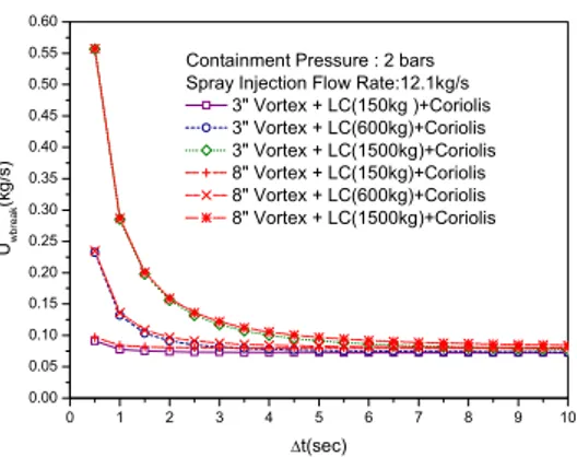
Break flow rate is measured in the containment system. Fig. 4 shows the instrumentations installed in the containment system. As shown in the figure, the water and steam flow rates are measured by the digital balances and vortex meters, respectively. In this containment system, a cold water injection system is equipped to condense the steam phase when its flow rate exceeds the measurements range of vortex flow meters. The estimated uncertainty of the measured break flow rate is dependent on the time difference of data acquisition. Fig.5 shows the estimated uncertainty according to the time difference of a measurement.
3. Conclusion
In this paper, an overall instrumentation system of ATLAS integral effect test facility was introduced. In the ATLAS test facility, more than 1,200 instrumentations are installed for the measurement of
3" SDS Discharge 6" MSLB 5" SG FW Break 3" DVI Line SBLOCA 5" LBLOCA(Vessel Side)
Load Cell Load Cell Load Cell Load Cell Load Cell
1500kg 600kg 600kg 600kg 150kg
Break Flow Separator 2 Break Flow
St e a m PT St e a m V TC V PT TC Separa tor 1 Load Cell Full Scale 3" 8" TC Water Flow Water Flow LC-CS-01 LC-CS-02 LC-CS-03 LC-CS-04 LC-CS-05 PT-CS-03 TF-CS-03 QV-CS-03 PT-CS-01 TF-CS-01 QV-CS-01 PT-CS-02 TF-CS-02 QV-CS-02 TF-CS-08 TF-CS-09 TF-CS-10 TF-CS-11 TF-CS-12 TC TF-CS-04 TC TF-CS-05 TC TC TF-CS-06 TF-CS-07 Coriolis TC Cold Water Injection(2") QM-CS-01 Rosemount CMS200 TF-CS-13 V 3" PT A B A A A B B From MWS PT PT PT-CS-04 PT-CS-05 5" LBLOCA(Pump Side) TF-BS-01C TF-BS-01D TC
Figure 4. Concept of Break Flow Measurement
0 1 2 3 4 5 6 7 8 9 10 0.00 0.05 0.10 0.15 0.20 0.25 0.30 0.35 0.40 0.45 0.50 0.55 0.60 Uwbr eak (k g /s) ∆t(sec) Containment Pressure : 2 bars Spray Injection Flow Rate:12.1kg/s
3" Vortex + LC(150kg )+Coriolis 3" Vortex + LC(600kg)+Coriolis 3" Vortex + LC(1500kg)+Coriolis 8" Vortex + LC(150kg)+Coriolis 8" Vortex + LC(600kg)+Coriolis 8" Vortex + LC(1500kg)+Coriolis
Figure 5. Uncertainty of Break Flow Rate According to the Time difference of Measurement
thermal hydraulics phenomena in the components. Most of the instrumentations are chosen from commercially available ones, however, an average BDFT and a break flow system are specially developed or designed for the measurements of mass and break flow rates in the primary piping and containment system, respectively.
REFERENCES
[1] W.P. Baek, C.-H. Song, B.J. Yun, T.S. Kwon, Sang.Ki. Moon and S.J. LEE, KAERI Integral Effect Test Program and
the ATLAS Design, To be published Nuclear Technology
.
[2] M. Ishii S.T.Revankarr, T.L.Leonardil, R.Dowlati, M.L.Bertodano,I.Babelli,W.WangH.Pokharna, V.H.RAansom, R.Viskanta and J.T.Han, The Three Level Scaling Approach with Application to the Purdue University Multi-dimensional Integral Test Assembly (PUMA), Nucl. Eng. Des., 186, 177 (1998).
[3] B.J.Yun, Design Requirement of Instrumentation System for the Integral Effect Test Facility, IET-IMS-DR001, Rev. 00, WS-1, 2003.
[4] B.J.Yun,I.C.Chu,K.H.Kang,S.Cho, D.J.Euh ,Design Report of the ATLAS Integral Effect Test Facility, ,ATLAS-IMS-DA001, Rev. 00, WS-2, 2003.
[5] B.J.Yun,,K.H.Kang,D.J.Euh, C.-H. Song, , W.P. Baek, Measurement of the Single and Two Phase Flow using a Newly Developed Average Bidirectional Flow Tube, Submitted to Nuclear Engineering and Technology, 2005.