Introduction
A rice transplanter is an indispensable machine for rice farming. In Korea, rice farming is completely mechanized and the mechanization of rice transplanter is appro-ximately 99.9% (Yu et al., 2015). At present, several problems such as low sustainability, brittleness and so on have been identified in the existing transplanter, and demand for mechanized rice transplanters in domestic and overseas markets is decreasing because of the technological gap with developed countries such as
Japan, USA and so on (Siddique et al., 2018). The most critical issue is that only the ascending descending system of existing rice transplanter is mechanized which is associated with the tilting of the planted seedlings. Given that an on/off valve, which does not able to perform precisely, was used to develop the existing model. It is necessary to use highly precise technology, such as proportional valve to replace the on/off valve, to enhance the comprehensive performance of rice transplanter.
Several articles have been published on transplanter applying hydraulic actuators and proportional valve. Hydraulic actuators are widely used in autonomous industry for their tolerance, density, and sizing, and hydraulic actuators can effectively control velocity using
Determination of PID Coefficients for the Ascending and Descending System
Using Proportional Valve of a Rice Transplanter
Md. Abu Ayub Siddique1, Wan-Soo Kim1, Seung-Yun Baek1, Yeon-Soo Kim1,2, Chang-Hyun Choi3, Yong-Joo Kim1*, Jin-Kam Park4
1Dept. of Biosystems Machinery Engineering, Chungnam National University, Daejeon, 34134, Republic of Korea 2Convergence Agricultural Machinery Group, Korea Institute of Industrial Technology, 119, Jipyeonmgseon 3-gil,
Baeksan-myeon, Gimje-si, Jeollabuk-do, 54325, Republic of Korea
3Dept. of Mio-Mechatronics Engineering, Sungkyunkwan University, Suwon, 16419, Republic of Korea 4LS Mtron Ltd. Tractor Advanced R/D group, Anyang, 14119, Republic of Korea
Received: October 31th, 2018; Revised: November 26th, 2018; Accepted: December 4th, 2018
Purpose: This study was conducted to develop a linear Proportional-Integral-Derivative (PID) control algorithm for the ascending and descending system of a rice transplanter and to analyze its response characteristics. Methods: A hydraulic model using a single-acting actuator, proportional valve and a PID control algorithm were developed for the ascending and descending system. The PID coefficients are tuned using the Ziegler-Nichols (Z-N) method and the characteristics of unit step response are analyzed to select the PID coefficients at various pump speeds. Results: Results showed that the performance of the PID controller was superior in any condition. It was found that the highest settling time and maximum overshoot were less than 0.210 s and 5%, respectively at all pump speed. It was determined that the steady state errors were 0% in all the cases. The lowest overshoot and settling time were calculated to be nearly 2.56% and 0.205 s, respectively at the pump rated speed (2650 rpm). Conclusions: The results indicated that the developed PID control algorithm would be feasible for the ascending and descending system of a rice transplanter. Finally, it would be helpful to plant the seedlings uniformly and improve the performance of the rice transplanter.
Keywords: Hydraulic actuator, PID controller, Proportional valve, Rice transplanter, Simulation J. Biosyst. Eng. 43(4):331-341. (2018. 12)
https://doi.org/10.5307/JBE.2018.43.4.331
eISSN : 2234-1862 pISSN : 1738-1266
*Corresponding author: Yong-Joo Kim
Tel: +82-42-821-6716; Fax: +82-42-823-6246 E-mail: babina@cnu.ac.kr
a proportional valve (Backe, 1993; Burrows, 1994). In addition, hydraulic actuators have various benefits such as low production cost, quick response, and a simple control algorithm (Song and Lee, 2015; Shin et al., 2015; Shin et al., 2013). Hydraulic proportional valves improved the performance and efficiency of the hydraulic servo or actuating system. Moreover, proportional valves are capable of efficiently operating the actuator during the field operation and provide optimal power control depending on workload. Zhu et al. (2012) reported that the hydraulic control system of a high-speed transplanter improved the stability and efficiency of transplanter. The simulation results displayed the real-time state graphs which revealed that the performance of a transplanter using hydraulic control system was stable, flexible, and comfortable in the field. However, the planting device needed to be operated manually. Wei et al. (2015) also applied a proportional valve to the manual control system of rice transplanter for autonomic navigation only. Lian et al. (2009) modified the transplanting control system, transmission, navigation, and variable operation of the Kubota rice transplanter with an electronic control system using a proportional valve instead of the manual control system. The results showed that the electronic control system of transplanter performed similar to a manual operating system.
In existing literature, it is found that the ascending and descending system using proportional valve of a rice transplanter has not been studied in detail. Some researchers have stated the advantages and reasons of the application of the hydraulic proportional valves and actuators in various agricultural machineries. The proportional valves improved the flexibility, increased the comfort of drivers and also saved energy (Zardin et al., 2018; Ahn et al. 2015; Borghi et al., 2014). The function of proportional valves is to supply a constant or required flow rate, and make manual or automatic adjustments utilizing the sensors, controllers and actuators (Lisowski and Filo, 2016; Bravo et al., 2017). This study also indicated that hydraulic companies and scientific research organizations are highly interested in pro-portional valves because they enable a smooth adjustable flow rate capacity. Therefore, the proportional valve is applied in the ascending and descending system of rice transplanter to control the flow rate as well as actuator displacement.
However, proportional valves as well as hydraulic
actuators have some unwanted characteristics such as nonlinearity, hysteresis, and asymmetric grain flow. The behavior of nonlinearity can change the system load and operating conditions (Zhang, 1999). According to Anderson (1988), the nonlinearity can impact the performance of the hydraulic system, accuracy of the control, and the stability of the hydraulic system. Therefore, a control algorithm is important to control those nonlinear properties of proportional valves or hydraulic actuating system.
There are several types of controllers to control the servo system such as fuzzy logic controller (Milecki and Rybarczyk, 2015), nonlinear control system using Lypunov function (Sohl and Bobrow, 1999), nonlinear robust control system (Guan and Pan, 2008), and PID controller (Rozali et al., 2010; Kim et al., 2016). Among them, proportional, integral, and derivative (PID) controller is the most common, and it is frequently used to control the hydraulic system in autonomous industries (Rozali et al., 2010). A PID controller is designed using a Laplace transformer (Shang, 2004). Simplicity, flexibility, and adaptability are the main advantages of the PID control algorithm (Jiangxue, 2017). In addition, the tuning coefficients of PID controllers are comparatively easier to determine using the Ziegler-Nichols methods. Therefore, the objectives of this study are i) to develop a PID controller for the ascending and descending system designed using the hydraulic proportional valve of a rice transplanter, ii) to analyze the response characteristics of the PID controller, and iii) to determine and optimize the PID coefficients.
Materials and Methods
Rice transplanter
Generally, rice transplanter has five important parts that are hydraulically interrelated with each other, namely,
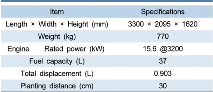
Table 1. Specifications of rice transplanter
Item Specifications
Length × Width × Height (mm) 3300 × 2095 × 1620
Weight (kg) 770
Engine Rated power (kW) 15.6 @3200
Fuel capacity (L) 37
Total displacement (L) 0.903 Planting distance (cm) 30
the engine, hydrostatic transmission, power assisted steering, horizontal control system, and ascending and descending system. The specifications of a rice trans-planter is listed in Table 1.
In this article, the ascending and descending system of a rice transplanter has been studied. The ascending and descending system has a float sensor, which controls the planting depth maintaining the height between soil and float. Transplanter performance depends on the actuator movement of the ascending and descending system. The
actuator displacement has two effects on the planted seedlings: the transplanter float pushes, and presses the soil. As a result, the planted seedlings tilt and finally, effect on the planting uniformly as well as transplanter performance. Therefore, it is a vital issue to control the actuator displacement of the ascending and descending system. The ascending and descending system of rice transplanter is shown in Figure 1.
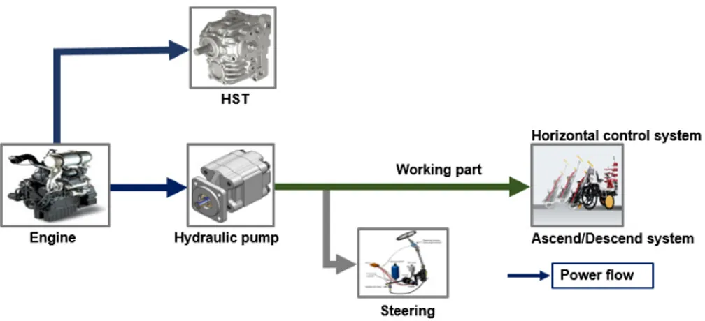
Power flow of rice transplanter
Engine power is divided into the hydrostatic trans-mission (HST) and hydraulic pump. Then power from the hydraulic pump is transmitted to the horizontal control system, and ascending and descending system through the power assisted steering mechanism. The principle of the power-assisted steering mechanism is that the steering force is geared up through the hydraulic circuit and helps turn the machine easily. Actually, the rotational speed and torque generated by the engine act on the hydraulic pump, and the flow rate generated by the pump supplies power to the hydraulic motor, resulting in driving the working institutions. The horizontal control system maintains a steady machine balance, and supplies plants to the planting institution continuously. Consequently, the ascending and descending system is associated with planting at the desired depth. A schematic diagram of the rice transplanter power flow is shown in Figure 2.
Block diagram of the ascending and
descending system
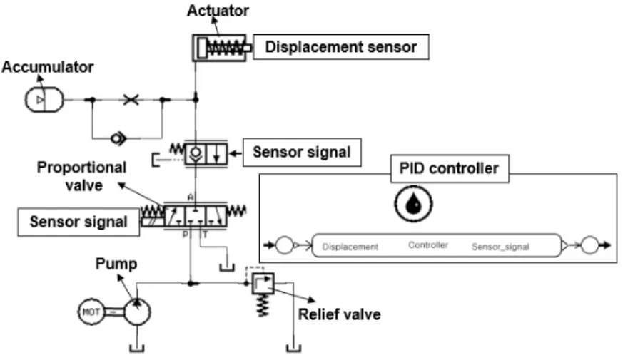
The ascending and descending system of the rice transplanter is developed based on the power flow of rice transplanter hydraulic system simulated by LMS AMESim (ver.: 16, Imagine S. A. company, France). The ascending
(a) Rice transplanter (Yanmar YR6D)
(b) Ascending and descending system
Figure 1. Ascending and descending system of rice transplanter.
and descending of rice transplanter is shown in Figure 3. The hydraulic proportional valve controls the flow rate supplied to the actuator, and the hydraulic actuator performs the ascending and descending by extending and retracting. The accumulator reserves the excessive fluid flow and supplies to the actuator in an emergency. The parameters of the hydraulic components were considered with respect to the actual rice transplanter. Specifications of the ascending and descending system of rice transplanter are listed in Table 2 (Siddique et al., 2018; Yoshida and Miyakawa, 2013; Amirante et al., 2013; Song and Lee, 2007; Zhang, 1999; Esposito, 1980). External load, nonlinear factors, asymmetric gain, and friction greatly affect the displacement tracking of the
ascending and descending system of the rice transplanter.
Design of controller for ascending and
descending system
Actuator model
In this study, a single acting hydraulic cylinder is used. Its velocity can be determined by the flow rate supplied to the actuator. A proportional valve is applied to regulate the flow rate, and the extending motion of the actuator is defined by flow community theory where the leakage and friction are omitted (Zhang, 2009; Zhang, 1999; Esposito, 1980). The flow rate supplied to the actuator is as follows.
Qa Ay′
vP′
(1) where Qa is the flow rate to the actuator (m3/s), A is the
cylinder area at the head end (m2), P is the cylinder
pressure at the head end (N/m2), V
1 is the volume of the
cylinder (m3), y is the displacement of the actuator (m), y’
and P’ are the 1st derivative form of actuator displacement
(y) and cylinder pressure, respectively, and β is the fluid bulk modulus (N/m2).
The single acting actuator retracting motion is accom-plished by using gravity or spring in the rod end.
PA KspringXact my″ F (2)
where Kspring is the spring rate (N/m), Xact is the length of
stroke (m), m is the mass of the actuator (kg), y’’ is the 2nd
derivative of y, and F is the external force acting on the cylinder (N).
The supplied flow rate to the head end of the actuator can be estimated by the orifice equation as described below. Table 2. Specifications of the ascending and descending system
Item Specifications
Actuator Piston diameter 55 mm
Rod diameter 15 mm
Spring preload 600 N Spring rate 40,000 N/m Pressure in rod chamber 2 bar Accumulator Gas precharge pressure 40 bar Accumulator volume 0.16 L Proportional valve Valve rated current 200 mA
Valve natural frequency 50 Hz Valve damping ratio 1.8
Valve gain 200
Pump displacement 4.5 cc/rev
speed 2650 rpm
Relief valve cracking pressure 242 bar
Density 850 kg/m3
Bulk modulus 17,000 bar
Qo CdAo
Ps P (3)
where Qo is the flow rate to the head end of the cylinder
(m3/s), C
d is the orifice coefficient, Ao is the valve orifice
area (m2), and P
s is the supply pressure of pump (N/m2).
The orifice area can be calculated by the following equation.
Ao Cgu (4)
where Cg is the gain coefficient of the solenoid valve, and
u is the control input voltage signal.
Therefore, the following equation is the flow rate to the head end of the actuator.
Qo Cfu
Ps P (5)Here, Cf CdCg
(6)
where Cf is the flow gain coefficient, and ρ is the fluid
density (kg/m3).
From equation (1) and (5), it is stated that Cfu
Ps P Av vP′
(7) Here, v is the velocity of the actuator, and neglecting spring back pressure for extending motion of actuator.
PA mv′ F (8)
Here, v’ is the 1st derivative of v, and equation (7) and
(8) provide the nonlinear state of the model. To get linearized formation, these equations are needed to make the differential equation using constant coefficient. The differential equations for linear actuator are below.
Kinputu KpressureP AvP′ (9)
PA mv′ (10)
The equations (9) and (10) can be applied to design the control algorithm for linear actuator.
Here, Kinput u Qs u uo (11) Kpressure p Qs p po (12) v (13)
where Kinput is the input signal, Kpressure is the gain factor of
cylinder chamber pressure, and δP, δQs, and δv are the
increment of cylinder pressure, pump flow supply, and actuating velocity, respectively. γ is the dumping factor.
The dynamic model for the hydraulic system is given as below.
m P′ KA inputu Ax′ KpressureP (14)
where δP’ is the increment of pressure changing rate in the cylinder, x’ is the velocity of the linear actuator, and δ x’ is the increment of cylinder velocity.
PID controller
Single acting actuator and proportional valve were the main concern. A controller was designed on the basis of transfer function of feedback control system. This type of controller stabilizes the system using a simple PID algorithm.
Gs K KsKs (15) where Kp, Ki, and Kd are the coefficients of proportional,
integral, and derivative, respectively. According to Isidori, (1989), the feedback linearization method is applied in equation (14) and the governing equation for single acting actuator is as follows.
VSus KinputA s ns n
n
(16) where ζ is the valve damping ratio, ωn is the valve
natural frequency of proportional valve which is denoted by Hz. According to Amirante et al., (2013), the range of natural frequency of a commercial proportional valve is 20 Hz to 85 Hz for the stabilization of the system. Kinput is
the input signal, and A is the cylinder area at the head end (m2). The values of the coefficients that are used to
determine Kinput are listed in Table 2.
Rice transplanters require faster rise time for the ascending and descending system. Yoshida and Miyakawa, (2013) reported that overdamping occurs when damping ratio is higher than 1, and overdamping assists in having a faster rise time. Equation (16) indicates a second-order system, which is used as a plant. It can control the velocity, i.e., flow rate as well as actuator displacement. The schematic block diagram of control algorithm is shown in Figure 4, in which a hydraulic system (Figure 3) developed using AMESim is installed by MATLAB/Simulink cosim interference.
PID coefficients simulation
The control algorithm for ascending and descending system of a rice transplanter was developed using MATLAB/ Simulink interferences (ver.: R2015a, MathWorks, USA). According to Choi et al. (2010), PID coefficients are carefully tuned, and the primary coefficients are selected by the Ziegler-Nichols (Z-N) method.
Kp TL (17)
Ki L
Kp
(18)
Kd Kp× L (19)
where L is the delay time (s), and T is the time constant (s) The Z-N method which is an open loop method, proposes procedures to determine the coefficients Kp, Ki,
and Kd using the equation (17) - (19). This method is
characterized two constants: one is the delay time (L) and another is the time constant (T). Those constants are calculated based on the tangent line drawn at inflection
point on the step response curve of the plant. Figure 5 shows the Z-N tuning method for unit step response.
In this study, pump rotational speed was considered as a variable. First, the rated revolution per minute (rpm) was determined using the minimum (1800) and maximum (3500) rpm and the total rpm range was divided into 4 levels of rpm. PID coefficients were determined at the pump rated speed. Finally, the selected coefficients at the pump rated speed was applied to the 4 levels of rpm.
Determination of optimal PID coefficients
The characteristics of unit step response such as maximum overshoot, settling time, and steady state error of PID controller were considered to select the PID coefficients. Settling time of an output is the required time to reach and stay within the range of the acceptable error band. The acceptable error band range is usually ±2% of the final value because the settling time is strongly related to the largest time constant of the control system (Ogata, 2002). Steady state error which is the difference between actual response and desired position after being controlled, is indicated at 0%. Percent
Figure 4. Schematic block diagram of PID controller for ascending and descending system.
overshoot is determined by the following equation. Overshoot MpF FV V× (20) where MP is the peak value of the time response, and Fv is
the final value of the response. For Figure 4, the final value of the response is 1.
Generally, the best or optimum coefficients are chosen on the basis of the overshoot, settling time, and steady state error values. The lower overshoot, settling time, and steady state error indicate the better performance of the actuating system (Kim et al., 2016). The selected coefficient at the rated pump speed was applied for the 4 levels of rpm (1800, 2225, 3075, and 3500) for the stability test and/or evaluating the performance of the controller. Characteristics of unit step response are shown in Figure 6.
Results and Discussion
Determination of PID coefficients
The performance of the PID controller has been conducted under various conditions. The actuator displacement was
tracked using the PID controller at 5 determined pump speed levels (1800, 2225, 2650, 3075, and 3500 rpm) for step reference signal. The controller has been used for the changing internal gain of hydraulic system. The controller was also capable of compensating the nonlinearity (temperature) including saturation and friction for satisfactory performance, that verified the linear PID control system. Table 3 represents the tuned PID coefficients including maximum overshoot, settling time, and steady state error that were analyzed for selecting the optimum PID coefficients. It was found that the steady state error was 0% for all conditions. It was also found that the average settling time and maximum overshoot were approximately 0.208 s and 3.766%, respectively. However, the lowest settling time and overshoot at the pump rated speed were calculated as approximately 0.205 s and 2.56%, respectively for Kp:5.24, Ki:4.39, and Kd:1.34. On
the other hand, the highest settling time and overshoot were almost 0.210 s and 4.87%, accordingly for Kp:3.50,
Ki:2.45, and Kd:1.12.
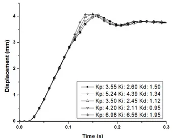
It is noticed that the displacement tracking of hydraulic actuator raised dramatically and stayed between the acceptable error band within 0.210 s for each coefficient
Figure 6. Characteristics of unit step response.
Table 3. Determination of PID coefficients at the pump rated speed
RPM Kp Ki Kd Max. overshoot (%) Settling time (s) Steady state error (%)
2650 (Rated) 3.55 2.60 1.50 3.85 0.210 0 5.24 4.39 1.34 2.56 0.205 0 3.50 2.45 1.12 4.87 0.210 0 4.20 2.11 0.95 2.58 0.206 0 6.98 6.56 1.95 4.97 0.209 0 Average 3.766 0.208 0
at the rated pump speed, shown in Figure 7, and the maximum overshoot was less than 5%.
Kim et al., (2016) stated the lowest values of the settling time, overshoot and steady state error that are referred to as the best performance of the actuating system. These results indicate that the controller can compensate the unexpected inherent parameters of the hydraulic system with accuracy.
Stability test of the controller
The selected coefficient at the pump rated speed was applied for all level of the pump rotational speeds, listed in Table 4. It is found that the best performance of the PID controller was at the pump rated rotational speed among all levels of rpm. Approximately 0.205 s of the settling time and 2.56% of the max. overshoot were the lowest. However, the highest values of the settling time and overshoot were almost 0.210 s and 4.97%, respectively at 1800 rpm.
The stability test results are also revealed that the max. overshoot and steady state error were less than 5% and 1%, respectively. In addition, settling time was also less
than 0.210 s shown in Figure 8. Li et al., 2017 reported that settling time was 4.5 s, and there was no overshoot and steady state error for hydraulic proportional valve in the position control mode. This study also reported that in the case of traction control mode of proportional valve, settling time was 4.5 s, there was small overshoot and no steady state error. This study showed that the simulation results are realistic for agricultural machines.
Kim et al., (2016) reported that average settling time and max. overshoot were found 0.44 s and 2.51%, respectively for shuttle shifting actuator of Automated Manual Transmission (AMT). The steady state error was also calculated to be approximately 0.29%. Rice trans-planters are comparatively slower and more precise machines than tractors. Therefore, this control algorithm is applicable to the ascending and descending system of a rice transplanter.
However, the limitation of this study is that only a simulation model is used for evaluation. In future, it is necessary to conduct an actual field test for the validation of this control algorithm in a real rice transplanter. Finally, it can be seen that the developed PID controller could be feasible for the ascending and descending system of a rice transplanter.
Conclusions
This study was conducted to develop a linear PID control algorithm and select the optimum PID coefficients for the ascending and descending system of a rice transplanter to improve its stability, comfort and accuracy. To control the displacement tracking of a hydraulic actuator and proportional valve, a PID controller was applied. A hydraulic simulation model and a control algorithm were developed using the electro hydraulic proportional valve. To study the performance of PID controller, 5 sets of coefficients were determined at the rated pump speed and the optimum coefficients were selected for the stability test. The test results of this study showed that the steady state error was 0% (zero) at all conditions. It is found that the highest settling time and max. overshoot were less than 0.210 s and 5% at all level of pump speeds. This controller can suitably compensate the effects of nonlinear gains of the hydraulic system. The results indicated that the developed PID control algorithm could be useful for the ascending and descending system of a rice transplanter. Finally, this control algorithm could Table 4. Results of applying the selected coefficients to each
engine revolution speed
RPM Max. overshoot (%)
Settling time (s)
Steady state error (%) 1800 4.97 0.210 0 2225 3.85 0.207 0 2650 2.56 0.205 0 3075 4.61 0.208 0 3500 4.36 0.209 0
be helpful in minimizing the tilting of seedling planted using the rice transplanter. Ultimately, it would uniformly improve the transplanter performance.
Conflict of Interest
The authors have no conflicting financial or other interests.
Acknowledgements
This work was supported by Korea Institute of Planning and Evaluation for Technology in Food, Agriculture, Forestry and Fisheries (IPET) through the Advanced Production Technology Development Program, funded by Ministry of Agriculture, Food and Rural Affairs (MAFRA) (317014-3).
References
Ahn, S., J. Choi, S. Kim, J. Lee, C. Choi and H. Kim. 2015. Development of an integrated engine-hydro-mechanical transmission control algorithm for a tractor. Advances in Mechanical Engineering 7(7): 1-18.
https://doi.org/10.1177/1687814015593870 Amirante, R., A. Lippolis and P. Tamburrano. 2013.
Theoretical and experimental analysis of a coupled system proportional control valve and hydraulic cylinder. Universal Journal of Engineering Science 1(2): 45-56.
Anderson, W. R. 1988. Controlling Electrohydraulic Systems. New York, USA: Marcel dekker.
Backé, W. 1993. The present and future of fluid power. Journal of System and Control Engineering 207(4): 193-212.
https://doi.org/10.1243/PIME_PROC_1993_207_343_02 Borghi, M., B. Zardin, F. Pintore and F. Belluzzi. 2014.
Energy savings in the hydraulic circuit of agricultural tractors. Energy Procedia 45(2014): 352-361. https://doi.org/10.1016/j.egypro.2014.01.038 Bravo, W. A., E. Canuto, M. Agostani and M. Bonadei. 2017.
Proportional electro-hydraulic valves: An embedded model control solution. Control Engineering Practice 62(2017): 22-35.
http://doi.org/10.1016/j.conengprac.2017.01.013
Burrows, C. R. 1994. Fluid power-progress in a key technology. JSME International Journal 37:691-701. Choi, C. H., M. N. Woo, D. H. Lee, Y. J. Kim and J. H. Jeong.
2010. Development of electric actuator position control system for automatic shuttle shifting of tractor. Journal of Biosystems Engineering, 35(4): 224-230 (In Korean, with English abstract).
https://doi.org/10.5307/JBE.2010.35.4.224
Esposito, A. 1980. Fluid Power with Application. 7th ed. New Jersey, USA: Pearson prentice hall.
Guan, C. and S. Pan. 2008. Nonlinear adaptive robust control of single rod electrohydraulic actuator with unknown nonlinear parameters. IEEE Transactions on Control Systems Technology 16(3): 434-445. https://doi.org/10.1109/TCST.2007.908195
Isidori, A. 1989. Nonlinear Control Systems. New York, USA: Springer Verlag.
Jiangxue, C. 2017. Research on hydraulic suspension technology of tractor. In: Proceedings of the 6th Inter-national Conference on Measurement, Instrumentation and Automation (ICMIA2017), pp.552-555, Zhuhai, China: June 2017.
Kim, Y. J., S. O. Chung, D. H. Lee, C. H. Choi and W. S. Kim. 2016. Automatic clutch control for automated transmission of agricultural tractor. In: Proceedings of the 8th international symposium on machinery and mechatronics for agriculture and biosystems engineering (ISMAB), pp. 80-85. Niigata, Japan: June 2016.
Li, M., L. Wang, J. Liu and J. Ye. 2017. Method study on fuzzy-PID adaptive control of electric hydraulic hitch system. AIP Conference Proceedings 1820(1): 07008- 1-07008-8.
http://doi.org/10.1063/1.4977350
Lian, H., L. Xiwen, Z. Zuoxi, Z. Zhigang, H. Junwan and C. Bin. 2009. Design of electronic control device and control algorithm for rice transplanter. Transaction of the Chinese Society of Agricultural Engineering 25(4): 118-122 (In Chinese, with English abstract). Lisowski, E. and G. Filo. 2016. CFD analysis of the
characteristics of a proportional flow control valve with an innovative opening shape. Energy Conversion and Management 123(2016): 15-28.
https://doi.org/10.1016/j.enconman.2016.06.025 Milecki, A. and D. Rybarczyk. 2015. Modelling of an
electrohydraulic proportional valve with a synchronous motor. Journal of Mechanical Engineering 61(9): 517-522.
https://doi.org/10.5545/sv-jme.2015.2553
Ogata, K. 2002. Modern Control Engineering, 4th ed. New Jersey, USA: Prentice-Hall, Inc.
Rozali, S. M., M. F. Rahmat, N. A. Wahab, R. Ghazali, and Zulfatman. 2010. PID controller design for an industrial hydraulic actuator with servo system. In: Proceedings of 2010 IEEE Student Conference on Research and Development, pp. 218-223, Putrajaya, Malaysia: December 2010.
Shang, T. 2004. Improving performance of an energy efficient hydraulic circuit. MS thesis. Saskatoon, Saskatchewan, Canada: Department of Mechanical Engineering, University of Saskatchewan.
Shin, B. H., D. Oh and S. Y. Lee. 2013. A two-dimensional laser scanning mirror using motion-decoupling ele-ctromagnetic actuators. Sensors 13(4): 4146-4156. https://doi.org/10.3390/s130404146
Shin, B. H., K. M. Lee and S. Y. Lee. 2015. A miniaturized tadpole robot using an electromagnetic oscillatory actuator. Journal of Bionic Engineering 12(1): 29-36. https://doi.org/10.1016/S1672-6529(14)60097-4 Siddique, M. A. A., W. S. Kim, S. Y. Beak, Y. J. Kim and C. H.
Choi. 2018. Simulation of hydraulic system of the rice transplanter with AMESim software. In: 2018 ASABE Annual International Meeting, Paper No. 201800981. St. Joseph. MI, USA: ASABE.
Sohl, G. A. and J. E. Bobrow. 1999. Experiments and simulations on the nonlinear control of hydraulic servosystem. IEEE Transactions on Control Systems Technology 7(2): 238-247.
https://doi.org/10.1109/87.748150
Song, C. W. and S. Y. Lee. 2015. Design of a solenoid actuator with a magnetic plunger for miniaturized segment robots. Applied Sciences 5(3): 595-607. https://doi.org/10.3390/app5030595
Song, C. S. and S. H. Lee. 2007. A study on the design of a hydraulic shift actuator of an AMT. Journal of the Korean Society for Precision Engineering 24(10): 75-82.
Wei, L., X. Zhang, Q. Jia and Y . Liu. 2015. Automatic Navigation System Research for PZ60 Rice Planter. International Conference on Computer and Computing Technologies in Agriculture 452: 653-661.
https://doi.org/10.1007/978-3-319-19620-6_73 Yoshida, F. and S. Miyakawa. 2013. Effect of design
parameters on response characteristics of water hydraulic proportional control valves. In: Proceeding of the 13th scandinavian international conference on fluid power (SICFP), pp. 429-436, Linkoping, Sweden. Yu, S. C., S. Y. Shin, C. H. Kang, B. G. Kim and J. O. Kim. 2015.
Current status of agricultural mechanization in South Korea. In: 2015 ASABE Annual International Meeting, Paper No. 152189653. St. Joseph. MI, USA: ASABE. Zardin, B., M. Borghi, F. Gherardini and N. Zanasi. 2018.
Modelling and simulation of a hydrostatic steering system for agricultural tractors. Energies 11(1): 230. https://doi.org/10.3390/en11010230
Zhang, Q. 1999. Hydraulic linear actuator velocity control using a feedforward-plus-PID control. International Journal of Flexible Automation and Integrated Manufacturing, 7(3): 277-292.
Zhang, Q. 2009. Basics of hydraulic systems. New York, USA: Taylor & Francis group.
Zhu, W., Q. Zhao and X. Hu. 2012. Simulation study on hydraulic control system of high speed transplanter with SIMSAE. In: Proceeding of the 2nd International
conference on consumer electronics, communications and networks (CECNet), pp. 2858-2860, Yichang, China: April 2012.
List of Nomenclatures
Symbol Parameters Unit
Qa Flow rate to the actuator m3/s
Qo Flow rate to the head end of the cylinder m3/s
δQ Increment of pump flow supply
A Cylinder area at the head end m2
Ao Valve orifice area m2
P Cylinder pressure at the head end N/m2
δP Increment of cylinder pressure
δP’ Increment of pressure changing rate in the cylinder
V Volume of the cylinder m3
v Velocity of the actuator m/s
δv Increment of actuating velocity
β Fluid bulk modulus N/m2
Kspring Spring rate N/m
Xact Length of stroke m
m Mass of the actuator kg
F External force acting on the cylinder N
Cd Orifice coefficient
Cg Gain coefficient of the solenoid
Cf Flow gain coefficient
Ps Supply pressure of pump N/m2
u Control input voltage signal
ρ Fluid density kg/m3
Kinput Input signal
Kpressure Gain factor of cylinder chamber pressure
y Displacement of the actuator m
x’ Velocity of linear actuator m/s
δx’ Increment of cylinder velocity
γ Dumping factor
Kp Coefficient of proportional
Ki Coefficient of integral
Kd Coefficient of derivative
ωn Valve natural frequency Hz
ζ Valve damping ratio
T Time constant s
L Delay time s
MP Peak value of the time response