종속형 SOGI 기반 DFIG 풍력터빈의 개선된 회전자 속도 추정
누옌안탄, 이동춘
영남대학교 전기공학과
Improved Rotor Speed Estimation in DFIG Wind Turbine Systems Based on Cascaded SOGI
Anh Tan Nguyen and Dong-Choon Lee
Department of Electrical Engineering, Yeungnam University Abstract
-
In this paper, an improved rotor speed estimation inDFIG wind turbine systems based on a cascaded SOGI is proposed. Due to excellent harmonics and DC offset rejection capability of the cascaded SOGI, the accurate rotor speed estimation can be achieved despite the harmonics and sensing offset in DFIG currents. The simulation results have verified the validity of proposed method.
1. INTRODUCTION
The reliability of the doubly-fed induction generator (DFIG)-based wind turbine systems can be enhanced by the uses of sensorless control methods. Based on the rotor current found by the stator-side quantities, i.e., stator voltage and stator current, and the measured rotor current, the rotor position can be estimated [1]-[3]. At the normal conditions, the good estimations can be achieved by the uses of aforementioned methods. Their estimation performances, however, can be adversely affected by the harmonics in the stator and rotor currents under distorted grid conditions. In addition, the current sensing offset is a concern for those methods as well.
Due to excellent harmonic rejection capability, the second-order generalized integrator (SOGI) has attracted a great deal of attention. Based on SOGI, the extraction of the positive- and negative-sequence components of grid voltage for grid synchronization control has been proposed [4]. Recently, the application of SOGI to sensorless control in DFIG wind turbine systems has been suggested [5].
This paper proposes an improved speed estimation in DFIG wind turbine systems using the cascaded SOGI. Since the cascaded SOGI bahaves like an adaptive filter, the proposed speed observer can allow the accurate speed estimation in presence of harmonics and sensing offset in DFIG currents. The effectiveness of the proposed method is verified by the simulation results.
2. CONTROL OF DFIGWIND TURBINE SYSTEMS
In the DFIG wind turbine systems, the grid-side converter is responsible for maintaining the DC-link voltage and grid-side power factor at unity. At the same time, the maximum power point tracking (MPPT) algorithm can be carried out by the rotor-side converter [5].
3. PROPOSED SENSORLESS CONTROL METHOD
3.1. Cascaded SOGI Structure
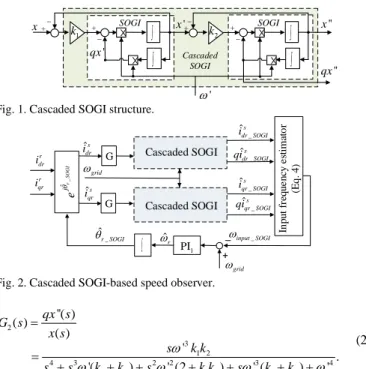
In the cascaded SOGI structure shown in Fig. 1, x is the input signal, x and '' qx are the output signals, which are in quadrature '' with each other, k1 and k2 are damping factors and ω'is the tuning
frequency.
The transfer functions of the cascaded SOGI are expressed as:
1 2 2 1 2 4 3 2 2 3 4 1 2 1 2 1 2 ''( ) ( ) ( ) ' '( ) ' (2 ) ' ( ) ' x s G s x s s k k s s k k s k k s k k ω ω ω ω ω = = + + + + + + + (1)
Fig. 1. Cascaded SOGI structure.
Fig. 2. Cascaded SOGI-based speed observer.
2 3 1 2 4 3 2 2 3 4 1 2 1 2 1 2 ''( ) ( ) ( ) ' . '( ) ' (2 ) ' ( ) ' qx s G s x s s k k s s k k s k k s k k ω ω ω ω ω = = + + + + + + + (2)
With an additional single SOGI used as pre-filter in the cascaded SOGI structure, the adverse effects of harmonics and DC offset in x onx and '' qx can be significantly mitigated. ''
3.2. Cascaded SOGI-based Speed Observer
Converting (1) and (2) into a time domain, the amplitude ratio of two cascaded SOGI outputs is obtain as:
'' ', '' qx x ω ω = (3)
where ωis the input frequency of cascaded SOGI.
As observed in (3), if the values of qx , '' x and '' ω'are known,
the estimation of ω can be achieved. Based on this idea, a cascaded
SOGI-based speed observer is proposed as shown in Fig. 2, in which, the frequency ωinput_SOGI and the gain G are expressed as:
(
) (
)
2 2 _ _ _ 2 2 _ _ ˆ ˆ ˆ ˆ s s dr SOGI qr SOGI input SOGI grids s dr SOGI qr SOGI i i qi qi ω =ω + + (4) 2 2 2 2 _ _ 늿 s s dr qr s s dr SOGI qr SOGI i i G i i + = + , (5)
where the d-q axis rotor current s dqr i is found by: s s dqs s dqs s dqr m L i i L λ − = . (6)
∫
x' ' ω ' qx 1 k SOGI x+ _ + _ ∫×
×
∫
'' x '' qx 2 k SOGI + _ + _ ∫×
×
Cascaded SOGI ˆs dr i _ ˆs dr SOGI i grid ω _ ˆs dr SOGI qi ∫ ˆs qr i _ ˆs qr SOGI qi _ ˆs qr SOGI i r dr i r qr i ∫ _ ˆ r SOGI θ grid ω _ input SOGI ω ˆr ω + _ _ +×
1 PI Cascaded SOGI Cascaded SOGI In put f re que nc y e st im at o r (Eq . 4 ) G G _ ˆr S OGI j e θ393
-전력전자학술대회 논문집 2020. 8. 18 ~ 20Fig. 3. Rotor position compensator.
In order to remove the effects of sensing offset in stator currents on estimation performances, the measured stator currents are filtered out through the cascaded SOGI-based filters with the tuning frequency at grid frequency.
3.3. Rotor Position Compensator
In the case of the unspecified initial rotor position as well as speed estimation error, it is necessary to add the compensation component
RPC
θ to θˆr_SOGI in Fig. 4 to correct the estimated rotor position. The
component θRPCis output of the rotor position compensator (RPC) as
shown in Fig. 3.
In proposed method, the estimated slip angle can be expressed as: θˆsl =θgrid−
(
θˆr_SOGI+θRPC)
. (7)4. SIMULATION RESULTS
Simulations of the proposed method for a 2 MW DFIG wind turbine system are performed in the PSIM platform. The system specifications are listed in Table I.
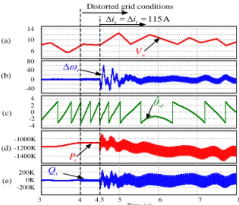
Figs. 4 and 5 show the system performances with applications of MRAS observer-based method [2] and proposed method under distorted grid conditions and DFIG current disturbance, respectively. For the grid distortion, the 5% fifth- and seventh-order harmonic components are included in each phase of grid voltage. The wind speed profile is shown in Fig. 4(a). Fig. 4(b) shows the speed estimation error ∆ . The estimated slip angle ˆωr θ is illustrated in sl
Fig. 4(c). Figs. 4(d) and (e) show the stator active power Ps and
reactive power Qs, respectively.
As observed from Fig. 4 and 5, the performances of two methods considered are similar under normal operating conditions. Under distorted grid condition and DFIG current disturbance, however, the proposed method gives the superior performances to the existing
method. The maximum of∆ωris about 60 rpm for the existing
method, whereas it is about 20 rpm for proposed method. When the current disturbance of 115 A is applied at t = 4.5 s, with the existing
method, the fluctuations of active power ΔPsand reactive power ΔQs
are about 380 kW and 400 kVAR, as shown in Fig. 4(d) and (e),
respectively. On the other hand, with the proposed method, ΔPs and
ΔQs are about 150 kW and 100 kVAR, as shown in Fig. 5(d) and (e),
respectively.
5. CONCLUSIONS
In this paper, an improved speed estimation in DFIG wind turbine systems has been proposed, based on cascaded SOGI. Due to excellent harmonics and DC offset rejection capability of cascaded SOGI, the good rotor speed estimation can be achieved even under grid voltage distortion and DFIG current disturbances. Under those conditions, the simulation results have shown that the maximum of
Fig. 4. System performances with MRAS observer-based method [2] under distorted grid conditions and current disturbances. (a) Wind speed (m/s). (b) Speed estimation error (rpm). (c) Estimated slip angle (rad). (d) Stator active power (W). (e) Stator reactive power (VAR).
Fig. 5. System performances with proposed method under distorted grid conditions and current disturbances. (a) Wind speed (m/s). (b) Speed estimation error (rpm). (c) Estimated slip angle (rad). (d) Stator active power (W). (e) Stator reactive power (VAR).
r
ω
∆ for the proposed method is about 20 rpm (about 1.11% of
measured speed).
ACKNOWLEDGMENTS
This work was supported by the Korea Institute of Energy Technology Evaluation and Planning (KETEP) and the Ministry of Trade, Industry & Energy (MOTIE) of the Republic of Korea (No. 20173030024770).
REFERENCES
[1] R. Datta and V. T. Ranganathan, “A simple position-sensorless algorithm for rotor-side field-oriented control of wound-rotor induction machine,” IEEE Trans. Ind. Electron., vol. 48, no. 4, pp. 786–793, Aug. 2001.
[2] A. B. Ataji, Y. Miura, T. Ise, and H. Tanaka, “A rotor-current-based slip angle estimator for grid-connected doubly fed Induction generator requiring the stator inductance only,” IEEE Trans. Power Electron., vol. 32, no. 6, pp. 4827–4838, Jun. 2017.
[3] S. Yang and V. Ajjarapu, “A speed-adaptive reduced-order observer for sensorless vector control of doubly fed induction generator-based variable-speed wind turbines,” IEEE Trans. Energy Convers., vol. 25, no. 3, pp. 891–900, Sep. 2010.
[4] P. Rodríguez, A. Luna, R. S. Muñoz-Aguilar, I. Etxeberria-Otadui, R. Teodorescu, and F. Blaabjerg, “A stationary reference frame grid synchronization system for three-phase grid-connected power converters under adverse grid conditions,” IEEE Trans. Power Electron., vol. 27, no. 1, pp. 99–112, Jan. 2012.
[5] A. T. Nguyen and D.-C. Lee, "Sensorless control scheme of DFIG wind energy conversion systems based on SOGIs and FLL," in Proc. of IEEE 10th International Symposium on Power Electronics for Distributed
Generation System (PEDG), Jun. 2019, pp. 465-471.
∫
B _ s dr SOGI i s qr i s dr i RPC j eθ _ s dr sh i 0 C θRPC + _ + _×
2 PI 3 4 5 6 7 8 Time (s) 0K -200K 200K 0 -2 -4 2 4 0 -40 40 80 6 10 14 -1400K -1200K -1000K w V r ω ∆ ˆ sl θ s P s Q (a) (b) (c) (d) (e)Distorted grid conditions
115 A s r i i ∆ = ∆ = 4.5 w V r ω ∆ ˆ sl θ s P s Q
Distorted grid conditions 115 A s r i i ∆ = ∆ = 3 4 5 6 7 8 Time (s) 4.5 0K -200K 200K 0 -2 -4 2 4 0 -40 40 80 6 10 14 -1400K -1200K -1000K (a) (b) (c) (d) (e)
TABLE I. Parameters of DFIG
Parameters Values
Stator frequency 60 Hz
Rated stator power 2 MW
Rated torque 10.6 × 10³ Nm
Rated line-line stator voltage 690 V
Rated stator current 1670 A