ICCAS2005 June 2-5, KINTEX, Gyeonggi-Do, Korea
1. INTRODUCTION
The rehabilitation for the handicapped is a big social issue in the world. There were many studies about assistive devices for the handicapped. Especially, the prosthetic legs and hands were representative assistive devices for the amputees. The prosthesis hands for the upper limb amputee are either the hook or the hand-shaped which are actuated by either body or external power. The body-powered hand including the hook is robust, lightweight and lower in cost, but it needs the body power. The myoelectric hand is a prosthesis actuated by external power. Therefore such myoelectric hand is more comfortable and cosmetically attractive than body-powered hand because it needs no cable-pulls [8].
Myoelectric hand prostheses controlled by the myoelectric signals had been developed in USA [6] and EU [5]. The myoelectric signal generated by voluntary contraction of the residual muscle is regarded as an intention of the myoelectric hand user. Generally, the user’s intention is recognized by comparing a mean absolute value (MAV) of the myoelectric signal with a predetermined threshold value. Currently, most myoelectric hands have the finger grasping and wrist rotation function similar to normal person’s hand motion. This is one of the biomimetic system controlled by the voluntary contraction of the residual muscle [3].
Therefore, surface myoelectric sensor (SMES) for measuring the myoelectric signal is an important component for the myoelectric hand prosthesis. The SMES is fitted in the socket of the prosthesis hand. When user puts the stump in the socket, the SMES is attached to the skin on the residual muscle of the stump. However, the output of SMES is easily affected in a wet condition due to the sweat and the humidity, because the impedance between the skin and the electrode of the SEMS changes in the wet condition. The power-line noise makes an increase of the output offset voltage. Thus the signal processing circuit should have a good SNR property.
This paper proposes a compact-sized SMES with good SNR property for the myoelectric hand prosthesis. The SMES is composed of a skin interface and a single processing circuit
that are mounted on a single package. The skin interface has one reference and two input electrodes, and the reference electrode is located in the middle of two input electrodes. We propose two types of sensors with the circle- and bar-shaped reference electrode, but all input electrodes are the bar-shaped. The metal material used for the electrodes is the stainless steel (SUS440) that endures sweat and wet conditions. Considering conduction velocity and median frequency of the myoelectric signal, we select the inter-electrode distance (IED) between two input electrodes as 18mm, 20mm, and 22mm. The signal processing circuit for the SMES consists of a differential amplifier with band pass filter (BPF) and a band rejection filter (BRF) for rejecting a power-line noise, amplifiers, and a MAV circuit.
Using a frequency analysis of the myoelectric signal taken from an able-subject we evaluate the proposed SMES from the output characteristics according to the IED and the shape of the reference electrode. The output signal of the proposed SMES is also compared with a commercial SMES when a virtual myoelectric signal is given. From the experimental results we show the surface myoelectric sensor with the 18mm IED and the bar-shaped reference electrode is suitable for the myoelectric hand prosthesis.
2. SURFACE MYOELECTRIC SENSOR
2.1 Myoelectric signal
The impulse generated by motion intention is sent from the brain to a muscle fiber via motor neuron in the spinal cord. When the impulse reaches to the muscle fiber, an electrical activity is occurred, and then muscle is contracted. The muscle contraction is a result of the electrical stimulation transferred from the nerve to individual muscle fibers. The conduction velocity of the muscle fiber is known as 2~6m/sec [2]. The amplitude of the myoelectric signal measured from the surface ranges from 0 to 10mV [4], and the frequency of the myoelectric signal is distributed between 0Hz to 10 kHz, but most energies of the signal are concentrated in the range of 30Hz to 500Hz. The median frequency is 86Hz, and it changes
Development of Surface Myoelectric Sensor for Myoelectric Hand Prosthesis
Gi-Won Choi, Inhyuk Moon, So-Young Sung, Mynug-Joon Lee, Jun-Uk Chu, and Mu-Seong Mun.
Korea Orthopedics & Rehabilitation Engineering Center (KOREC), INCHEON 403-712, KOREA (Tel : +82-32-500-0580; E-mail: gwchoi@iris.korec.re.kr)
Abstract: This paper proposes a compact-sized surface myoelectric sensor for myoelectric hand prosthesis. To fit the surface
myoelectric sensor in the socket of the myoelectric hand prosthesis, the sensor should be a compact size. The surface myoelectric sensor is composed of a skin interface and a single processing circuit that are mounted on a single package. Since the skin interface has one reference and two input electrodes, and the reference electrode is located in middle of two input electrodes, we propose two types of sensors with the circle- and bar-shaped reference electrode, but all input electrodes are the bar-shaped. The metal material used for the electrodes is the stainless steel (SUS440) that endures sweat and wet conditions. Considering conduction velocity and median frequency of the myoelectric signal, we select the inter-electrode distance (IED) between two input electrodes as 18mm, 20mm, and 22 mm. The signal processing circuit consists of a differential amplifier with band pass filter, a band rejection filter for rejecting 60Hz power-line noise, amplifiers, and a mean absolute value circuit. We evaluate the proposed sensor from the output characteristics according to the IED and the shape of the reference electrode. From the experimental results we show the surface myoelectric sensor with the 18mm IED and the bar-shaped reference electrode is suitable for the myoelectric hand prosthesis.
Keywords: surface myoelectric sensor, myoelectric hand prosthesis, electrode shape, inter-electrode distance
ICCAS2005 June 2-5, KINTEX, Gyeonggi-Do, Korea
signal processing circuit
MAV signal
Myoelectric signal
+ -G
differential amp with BPF
Ref. MAV circuit BPF 32dB out V line V V2+ line r V V+ line V V1+ Hz wo=60 Hz w1=4 Hz w2=900 o w 1 w w2 VR BRF 60dB gain o w electrode AC coupled Amplifier clamper peak det. integrator Hz wo=60 Line noise
skin interface signal processing circuit
MAV signal
Myoelectric signal
+ -G
differential amp with BPF
Ref. MAV circuit BPF 32dB out V line V V2+ line r V V+ line V V1+ Hz wo=60 Hz w1=4 Hz w2=900 o w 1 w w2 VR BRF 60dB gain o w electrode AC coupled Amplifier clamper peak det. integrator Hz wo=60 Line noise skin interface
Fig. 1 Block diagram for SMES.
to 112Hz when the white noise is added [1]. Therefore we select 90 Hz, 100 Hz, and 110Hz as the typical median frequency of the myoelectric signal, and determine an optimal IED based on the conduction velocity and the typical median frequency of the myoelectric signal.
2.2 Design of circuit
Since the signal reference electrode of the SMES contacts with the skin, the myoelectric signal measured contains a common mode noise induced through the body. And the amplitude of the myoelectric signal easily changes according to the conditions of the residual muscles. Therefore, the SMES must have a high common mode rejection ratio (CMRR) and a good SNR property.
Figure 1 shows the block-diagram of the proposed SMES. We use a rechargeable 7.2V lithium battery as the input power source, and the bipolar power source in the circuit is made of a voltage division circuit with a virtual ground. Accordingly, amplifiers that can be driven by lower voltage are used for the SMES. As shown in Fig. 1, the differential amplifier is first employed in taking the myoelectric signal from two input electrodes of the skin interface. The reference electrode is connected to the virtual ground, and it is equivalent to the common ground. The differential amplifier has 32dB gain, and it is composed of a BPF with the 4 to 900Hz bandwidth. Using the differential amplifier, we first obtain raw myoelectric signal
out
V to be eliminated the common mode noise, as
follows: )}] ( ) {( )} ( )
[{( 1 line r line 2 line r line
out G V V V V V V V V V = + − + − + − + ) (V1 V2 G − = (1)
where V1 and V2 are the two inputs measured, and Vr and G is
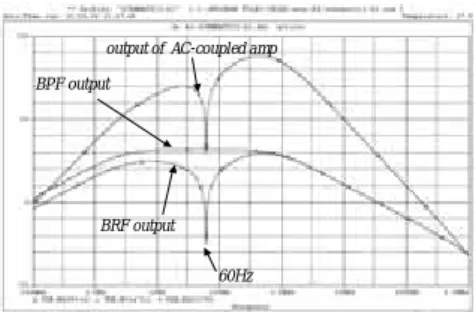
the signal common and the gain, respectively. The 60Hz power-line noise induced through the body can be measured. To eliminate the power-line noise a BRF with 60Hz cut-off frequency is built in the next stage of the differential amplifier. To reduce the sensor size we only use passive elements such the resistance and the capacitance for the BRF. The designed BRF had –60dB attenuation at the 60Hz, but the notch bandwidth was large. Therefore we used an AC-coupled
60Hz BPF output
output of AC-coupled amp
BRF output
60Hz BPF output
output of AC-coupled amp
BRF output
Fig. 2 Bode plot of the designed signal processing circuit.
h1 w1 d1 d1 k ø h1 w1 d1 d1 k d2 d2 t1 t2 h1 w1 d1 d1 k ø h1 w1 d1 d1 k d2 d2 t1 t2
Fig. 3 Shape and dimension of the designed skin interfaces. amplifier with 60dB gain for compensating the unexpected attenuation by the BRF. And then a variable resistance is set in the input of the AC-coupled amplifier to control the MAV output. The MAV circuit is made of a clamper and a peak detector. As a result, the final MAV output is the signal on the basis of the source ground.
Figure 2 shows the Bode plot of the designed circuit. The maximum gain was 88dB at 300Hz, and the gain at 30Hz was about 70dB. Since the real maximum output is less than the source voltage, the final output in the high frequency region has 70dB gain similar to the low frequency gain.
2.3 Design of skin interface
To realize a small size SMES, the skin interface of the SMES attached on the skin directly should be a compact size. We designed a skin interface with two input electrodes and one reference electrode mounted on a single package. The reference electrode designed was put on the middle of two input electrodes. The implemented electrodes in this paper had two types of skin interface of which the reference electrode is the circle-shaped electrode called A-type and the bar-shaped electrode called B-type, but all input electrodes are the bar-shaped. Figure 3 shows the shape and the dimension of the designed skin interfaces. The sizes of the bar-type electrode
are w1=5.5mm and h1=9.5mm, and the diameter of the circle
electrode is φ=10mm. The inter-electrode distance (IED)
k(=2d1) of the skin interface is designed by considering the
median frequency and the conduction velocity of the myoelectric signals.
2.4 Design of IED
In this study we assume that the conduction velocity of the muscle fiber, v [mm/sec], is uniform in the same muscle unit, and that the myoelectric signal propagates from the end of the motor nerves to a ligament along the fiber. Therefore, the myoelectric signals measured by each input electrode have a
time delay, k v [sec], due to the IED. Assuming that f0 is a
frequency of the measured myoelectric signal, a phase
difference, θd [rad], between the measured myoelectric
signals must be occurred by the time delay. This phase difference can be expressed as the following equation.
v k fo
d π
θ =2 (2) Generally if the phase difference between two input signals
with the same electric potential is θd =2nπ (n=1,2,3,...),
the output is eliminated by the property of the differential amplifier (see the dotted line in Fig. 4). Therefore we can obtain the relationship between the IED and the common mode rejection as follows:
π π n v k fo 2 2 = (n=1,2,3,...) (3) From (3) we can calculate the IED, k, to eliminate the
common mode rejection when the signal frequency, f0, and the
conduction velocity, v, are given as the following equation.
ICCAS2005 June 2-5, KINTEX, Gyeonggi-Do, Korea
k + -differential amplifier k + -+ -differential amplifier
Fig. 4 Signal input to the differential amplifier.
o
f v n
k= (n=1,2,3...) (4)
Similarly, we can obtain the maximum output when the phase
difference is θd=noddπ (nodd=1, 3, 5 …) (see the solid line in
Fig. 4). As the same manner, the IED k to get the maximum output is calculated from (2) as the following equation.
k=nodd (v/f0)/2 (nodd=1, 3, 5, 7 …) (5)
In this study we set the conduction velocity v to 4 [m/sec] that is the same as the average velocity of the myoelectric signal,
and we selected the typical frequency f0 of the myoelectric
signals as 90Hz, 100Hz, and 110Hz. Based on these assumptions, the IED k to generate the maximum output is obtained as 22.2mm, 20mm, and 18.1mm. On the contrary, given the IED k and the conduction velocity v, we can
calculate the frequency fm to make the maximum output and
the frequency fc to eliminate the common mode noise from (4)
and (5) as follows:
Output of AC-coupled amplifier
MAV output Output of diff. Amp and BRF
(a) 60Hz.
Output of AC-coupled amplifier
MAV output
Output of diff. Amp and BRF
(B) 100Hz.
Output of AC-coupled amplifier
MAV output Output of diff. Amp and BRF
Output of AC-coupled amplifier
MAV output Output of diff. Amp and BRF
(c) 200Hz.
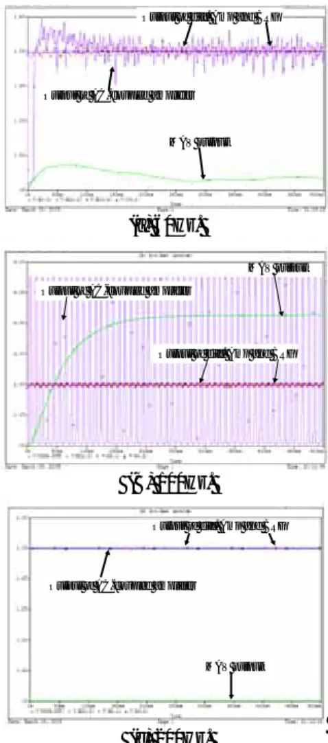
Fig. 5 Simulation results at each frequency.
fm =nodd v/(2k) (nodd=1,3, 5, 7 …) (6)
fc =n v/k (n=1,2,3,4 …) (7)
For instance, when k=20mm and v=4m/sec, fm and fc are
100Hz, 300Hz, 500Hz and 200Hz, 400Hz, 600Hz, respectively.
We performed a simulation according to the change of the signal frequency. In this simulation we gave the IED and the conduction velocity as k=20mm and v=4m/sec, respectively, and selected the signal frequency as 60Hz, 100Hz, and 200Hz. The amplitude of the input signal was set to 1mV. Fig. 5 shows the simulation results. At first we tested
f0=60Hz that is the same as the power-line noise. By the BRF
with 60Hz cutoff frequency the final MAV signal had 400mV
peak as shown in Fig. 5(a). Given f0=100Hz that is the same as
the fm to make the maximum output, the output of the
differential amplifier was 800 mV peak on the basis of the virtual ground, and the output of BRF was 32 mV. After the AC-coupled amplifier, the output was 5.5V peak. Finally, the MAV output was 4.2V peak on the basis of the source ground
(see Fig. 5(b)). At f0=200Hz that is the same as the fc to
eliminate the output, the MAV output was almost zero as shown in Fig. 5(c).
3. EXPERIMENTAL RESULTS
3.1 Experiments for IED
Fig. 6 shows the fabricated skin interfaces of which IEDs are 18mm, 20mm, and 22mm from the top, but the types of the reference electrode are the bar and the circle shape, respectively. All thickness of the skin interface in Fig. 3 was
t1=1.9mm and t2 =1.5mm.
To evaluate the skin interface according to the IED and the shape of the reference electrode we use the developed signal processing circuit with 25.5x16x5mm (WxHxD) to measure the myoelectric signal. Fig. 7 shows the developed PCB and the assembled SMES. In this experiment, the myoelectric signal is measured from the forearm of an able-subject. When measuring the myoelectric signal, the subject should keep on the voluntary contract of his forearm muscle uniformly. To ensure the uniform contraction, we make the subject to lift up 10kg dumbbell during 10 seconds. Then, the myoelectric signal measured by the SMES was sampled by 1024Hz rates using an ADC (PXI-6052E, NI Co.).
Fig. 6 Skin interfaces with different IED and shapes of the reference electrode shape.
Fig. 7 Developed PCB for signal processing and SMES assembled.
ICCAS2005 June 2-5, KINTEX, Gyeonggi-Do, Korea
0 100 200 300 400 500 -100 -90 -80 -70 -60 -50 -40 bar. k=18mm bar. k=20mm bar. k=22mm 0 100 200 300 400 500 -100 -90 -80 -70 -60 -50 -40 circle k=18mm circle k=20mm circle k=22mm
(a) A type. (b) B type.
Fig. 8 Spectrums of myoelectric signals measured from an able-subject using the skin interfaces with various IEDs.
Fig. 8 shows the spectrums of the measured myoelectric signal for each skin interface. The tendency of the spectrum of the skin interfaces with different IEDs showed similar results in the same reference electrode. However, the energy of the
maximum frequency fm was not larger than the other
frequencies. This is caused by the non-stationary property of the myoelectric signal [7]. Consequently, we can see the skin interface with 18mm IED is suitable for the SMES, because the smaller skin interface benefits to the implementation of the compact SMES.
3.2 Comparison with a commercial SMES
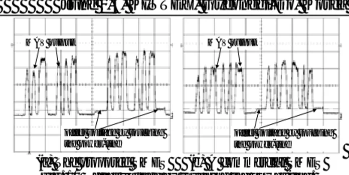
We also compared the developed SMES with a commercial SMES (13E125, Ottobock Co.) on the output properties when virtual signals and real myoelectric signals were given. To realize the virtual myoelectric signal, we implemented a signal generation system using an attenuator and DAC (PXI-6040E, NI Co.). The frequency of the virtual signal was controllable by software, and its amplitude was ±1mV peak-to-peak. Fig. 9 shows the MAV output when the 300Hz virtual myoelectric signal is given. Table 1 is the results of the comparison experiments between the developed and the commercial SMES according to the signal frequencies. We also compared the rising and falling time of the MAV output. The commercial SMES was 155msec and 199msec, respectively, but the developed SMES showed 167msec and 230msec, respectively. Since the myoelectric signal has about 300msec time delay from which user’s intention is given, the time less than 50msec is not affected to the detection of user’s intention.
virtual myoelectric signal MAV output
(a) The proposed SMES (b) A commercial SMES Fig. 9 Input virtual myoelectric signal and output the MAV. Table 1 Comparison of the MAV output according to the virtual signal frequencies.
Amplitude of MAV Output (V) Sine wave
frequency (Hz) Commercial SMES KOREC SMES
60 0.92 0.81 100 3.78 3.60 200 4.46 4.44 300 4.68 4.85 400 4.79 5.07 500 4.86 5.21 MAV output
offset voltage by touching the power-line
MAV output
offset voltage by touching the power-line
(a) The proposed SMES (b) A commercial SMES Fig. 10 Offset voltage by touching the power-line. Finally we performed a robustness test when the subject touched a power-line connected the wall socket of the 200V/AC. As a result, the developed SMES appeared 510mV offset voltage in the MAV output, but the commercial SMES had 620mV (see Fig. 10). Therefore the proposed SMES is more robust than the commercial SMES.
4. CONCLUSION
This paper proposed a compact-sized SMES for the myoelectric hand prosthesis. The SMES was composed of a skin interface and circuits mounted on a single package. We proposed two types of sensors with different shape of which the reference electrode was the circle- and bar-shaped, but all input electrodes were the bar shape. Based on the conduction velocity and the median frequency of myoelectric signal, we selected the IED as 18mm, 20mm, and 22mm, and compared the final output signals. From the experimental results we showed the surface myoelectric sensor with the 18mm IED and the bar-shaped reference electrode was suitable for the myoelectric hand prosthesis.
ACKNOWLEDGMENTS
This study was supported by a grant of the Korea Health 21 R&D Project, Ministry of Health &Welfare, Republic of Korea.(02-PJ3-PG6-EV03-0004)
REFERENCES
[1] D. J. Hewson, “Changes in impedance at the electrode-skin interface of surface EMG electrodes during long-term EMG recording,” proc. Of the 23rd
Annual EMBS Int’l conf., pp.3345-3348, 2001.
[2] C. J. De Luca, “Physiology and Mathematics of Myoelectric Signal,” IEEE Trans. Biomed. Eng., vol. 26, No. 6, 1997.
[3] Okuno, R., Yoshida, M., Akazawa, K., “Development of biomimetic prosthetic hand controlled by electromyogram.” Proc., of the 4th Advanced Motion
Control, AMC '96-MIE. Int’l. Workshop Vol. 1, pp. 103
– 108, 1996.
[4] Kumar, D.K.; Melaku, A., “Electrode Distance and magnitude of SEMG.” Proc., of the Second Joint EMBS/BMES Conf., vol. 3, pp. 2477 – 2480, 2002. [5] http://www.healthcare.ottobock.com./technical_orthoped
ics/armprothessen/sites/frame_myo.htm [6] http://www.utaharm.com.
[7] D. Farina, R. Merletti, “A Novel Approach for Estimating Muscle Fiber Conduction Velocity by Spatial and Temporal Filtering of Surface EMG Signals.” IEEE
Trans. Biomed. Eng., vol. 50, No. 12, 2003.
[8] http://www.healthcare.ottobock.com/info_download/pdf/ Elektroden_Text_GB.pdf