1. INTRODUCTION
SVG(Scalable Vector Graphics) a language for describing two-dimensional graphics in XML. SVG allows three types of graphic objects: vector graphic shapes (e.g., paths consisting of straight lines and curves), images and text. Graphical objects can be grouped, styled, transformed and composited into previously rendered objects. Text can be in any XML namespace suitable to the application, which enhances search ability and accessibility of the SVG graphics. The feature set includes nested transformations, clipping paths, alpha masks, filter effects, template objects and extensibility. SVG drawings can be dynamic and interactive.
SVG is a host language in terms of SMIL(Synchronize Multimedia Integration Language) Animation and especially introduces additional constraints and features as permitted by that specification. Except for any SVG-specific rules explicitly mentioned in this specification the normative definition for SVG's animation elements and attributes is the SMIL animation specification. the normative definition for SVG's animation elements and attributes is the animation specification.
SVG supports the following four animation elements(animate, set, animateMotion, animateColor) which are defined in the SMIL Animation specification.
Every day more organizations are being embraced CBD (component-based development) for its promise of code reusability and, as a result, reduced development effort and faster time-to-market.
CBD promises a more efficient way to develop applications with commercial, vendor-provided or internally developed objects. Using a visual development environment to test and assemble these objects significantly enhances productivity for all the members of the development team.
In this paper, we propose CBD method to figure component specification for SVG animation. It includes business type modeling, interface responsibility modeling, interface type modeling and component architecture modeling.
2. RELATED WORKS
DOM(Document Object Model) assigns various XML objects to variables. The variables can thus be accessed and manipulated by any number of applications. It is XML's tree structure that enables you to quickly retrieve the information or XML component you need. But it doesn't represents information about attribute and aggregation relationship. Besides that, there are XOMT diagram and UML class diagram in the area of DTD modelling method. XOMT, on
the basis of OMT object-oriented access, has too many parts that cannot be expressed by OMT itself, so extends OMT needs an extension. This requires that you learn another notation, and you will be not mapping class or the generalization concept used in the object model to semantic DTD. The modeling method using UML class diagram propose mapping rules from XML Document with links UML class diagram. It describes general mapping rules for XML DTD and Document Instance. It is not mapped to elements and documents for a special purpose. In case of RDF(Resource Description Framework), it doesn't map every element to class. According to kinds of RDF resource, it maps to relationships. In case of SMIL, it doesn't map synchronized tag to class. It represents synchronization through message between classes.
But the effect of SVG animations is variable according to time. We can not represent them using static class diagram.
It cab be used class diagram in step of conceptual modeling and component diagram for dynamic modeling of animation.
3. SVG Animation and UML
3.1 SVG Animation3.1.1 Animation element
SVG is a host language in terms of SMIL Animation and therefore introduces additional constraints and features as permitted by that specification. SVG supports the following four animation elements which are defined in the SMIL Animation specification.
(1) animate
It allows scalar attributes and properties to be assigned different values over time.
(2) set
A convenient shortabd for 'anamate', which is useful for assigning anamation values to non-numeric attributes and properties, such as the 'visibility' property.
(3) animateMotion
It moves an element along a motion path. (4) animateColor
It modifies the color value of particukar attributes or properties over time.
(5) animateTransform
It modifies one of SVG's transformation attributes over time, such as the 'transform' attribute.
3.1.2 Extended attribute
Additionally, SVG includes the following compatible extensions to SMIL Animation.
Component Modeling for SVG animation
Yan Ha, Hea-Sook, Park, and Soon-Mi Lee
School of Computer & Information, KyungIn Women’s College, Incheon, Korea (Tel : +82-32-5400-122; E-mail: {white, edpsphs, leesm}@kic.ac.kr)
Abstract: It has not been studied about modeling methods for SVG documents to represent animation in the web that has been recently increased in interest. In this paper, I propose component modeling for SVG documents by CBD methodology. First, I propose conceptual modeling by UML class diagrams for converting SVG document into component diagram. And then, I propose rules to convert the UML class diagram into component diagram.
Thus, main contribution of this paper is that it can generate a component diagram for a SVG document using Component-Based Development methodology.
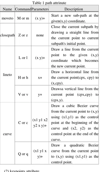
(1) path attribute
SVG allows any feature from SVG's path data syntax to be specified in a path attribute to the animationMotion element.
Table 1 path attrinute
Name Command Parameters Description
moveto M or m (x y)+ Start a new sub-path at the given(x,y) coordinate.
closepath Z or z none
Close the current subpath by drawing a straight line from the current point to current subpath's initial point.
L or l (x y)+
Draw a line from the current point to the given (x,y) coordinate which becomes the new current point. H or h x+
Draw a horizontal line from the current point(cpx, cpy) to (x,cpy).
lineto
V or v y+
Drawsa vertical line from the current point (cpx,cpy) to (cpx,y).
C or c (x1 y1 x2 y2 x y)+
Draw a cubic Bezier curve from the current point to (x,y) using (x1,y1) as the control point at the beginning of the curve and (x2, y2) as the control point at the end of the curve.
curve
Q or q (x1 y1 x y)+
Draw a quadratic Bezier curve from the current point to (x,y) using (x1,y1) as the control point.
(2) keypoints attribute
SVG adds a keyPoints attribute to the animateMotion to provide precise control of velocity of motion path animations.
(3) rotate attribute
SVG adds a rotate attribute to the animateMotion to control wether an object is automatically rotated so that its X-axis points in the same direction(or opposite direction) as the directional tangent vector of the motion path.
3.2 UML class diagram 3.2.1 class and stereotype
A class is an abstraction of the common properties from a set containing many similar objects. UML classes are being shown to use rectangles with the name of the class inside the rectangle. A variation uses a three-segment box; the top segment has the name of the class, the middle segment contains a list of attributes, and the bottom segment contains a list of operations.
A stereotype is the class of an entity in the UML metamodel. The UML metamodel is the model of UML itself, expresses in UML. Stereotypes provide an important extension mechanism to UML, allowing users to extend the modeling language to better address their needs. The usual
notation for stereotypes is to enclose the stereotype in guillemets proceding the name of the entity; for example "《type》stack, " which is the name of a class providing a stack interface for another implementation.’
3.2.2 association and composition
Associations are logically bidirectional unless explicitly constrained. A binary association is drawn as a solid path connecting two classifier symbols. An aggregation is a special type of association that implies logical or physical containment. Composition is a strong form of aggregation. Composition means that part objects are solely the responsibility of the composite class. Composition is showned by graphical inclusions of the components within the composite or with a filled in aggregation diamond.
3.3 UML component diagram
The component diagram's main purpose is to show the structural relationships between the components of a system.
3.3.1 component and Interface
A component represents a modular, deployable, and replaceable part of a system that encapsulates implementation and exposes a set of interfaces. A component is drawn as a rectangle with two smaller rectangles protruding from its left side.
An interface is a specifier for the externally -visible operations of a class, component, or other classifier (including subsystems) without specification of internal structure. An interface may also be displayed as a small circle with the name of the interface placed below the symbol. The circle may be attached by a solid line to classifiers that support it.
3.3.1 dependency and realization
A dependency indicates a semantic relationship between two model elements. It is shown as a dashed arrow between two model elements.
A realization is a kind of dependency relationship. It connects model element like interface to each component. A interface supply behaviral specification not structure and implementation.
4. SYSTEM
4.1 System architectureThe following figure is a system architecture that generates a component Diagram from SVG Document.
(1) Parser
XML parser checks syntax error and generates from SVG Document to DOM tree format.
(2) Business Type Modeller
It extracts business objects and defines attributes. And it represents composition relation with multiplicity.
We call ‘《core》’ business object in case of type to have business information that is continuously tracking and has independent identifier.
It needs to separate core business type and represents composition relations with multiplicity.
SVG Document
parser
parser
Business Type
Modeller
Business Type
Modeller
Interface
responsibility
modeller
Interface
responsibility
modeller
Interface Type
Modeller
Interface Type
Modeller
Component
Architecture
Modeller
Component
Architecture
Modeller
UML
Class Diagram
UML Component
Diagram
Component Diagram generatorFig1 System Architecture
(3) Interface Responsibility Modeller
It allocates one interface to core business object. And it is marked '1..n' multiplicity at composition relation. It has association relations using stereotype for animation tag.
(4) Interface Type Modeller
Interface type to manage core business object is inserted automatically get(), set() operations. In case of interface type for animation, It is inserted SVG attributes that has been transferred into operations.
(5) Component Architecture Modeller
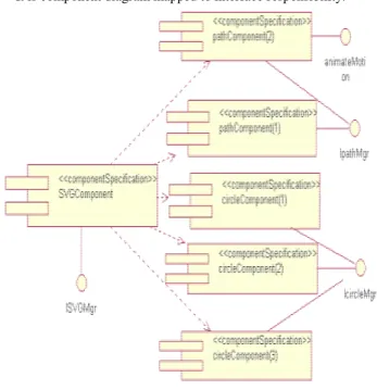
It generates each component for each core business object. The component has ‘《componentSpecification》’stereotype. And interface type has other notation and can be attached to component.
4.1.1 Generating of Business Type Model
Parsed SVG document generates class diagram by business type modeller. The rules are following.
[Rule 1] Element name to be start tag is class name and attribute is private attribute.
[Rule 2] It is attached ‘《core》’ stereotype to SVG, path, text and basic shapes element. SVG class become class.
[Rule 3] There is a composition relation between SVG class and another class.
[Rule 4] When it occurs one more same classes, it represents only one class with occurrence times.
The following algorithm is that it generates from SVG Document to business type model using mapping rules
━━━━━━━━━━━━━━━━━━━━━━━━━━━ It generates UML class diagram composed of classes and relations that is extracted from SVG document. It inserts attribute and value to class and multiplicity to composition.
4.1.2 Generating of Interface Responsibility Model It converts UML class diagram into interface responsibility model by algorithm for generating business type model
[Rule 5] It generates interface manager class of composition relation with 1..n multiplicity for '《core》’class.
Interface manager class has ‘《interface Type》’stereotype.
[Rule 6] Animation elements is to be class with ‘《interface Type》’stereotype and has association relations. The following algorithm is that it converts business type model to interface type model by using above rules.
Input: Business type model, SVG Document
Output: Interface Responsibility Model(UML class diagram)
begin {
for(number of 《core》 classes { // from Business type model generate 《interface Type》class make composition relations represent multiplicity }
for( animation element tags) { // from SVG document
generate 《interface Type》class make association relations represent multiplicity
} }
━━━━━━━━━━━━━━━━━━━━━━━━━━━ The following algorithm is that it generates interface responsibility model from business type model. It generates interface manager classes and attaches association relations. Input: SVG Document
Output: Business Type Model begin
{
Make a root class '《core》' // Make a SVG class for ( Number of attribute list ) insert attributes and values
for ( Numebr of start tags ) {
if (Path or Text or Basic shape) then {
if (The 《core》 class) update multiplicity else
{ generate 《core》 class for (Number of attribute list) insert attributes and values Composition relation } else { make class Composition relation } } } } end;
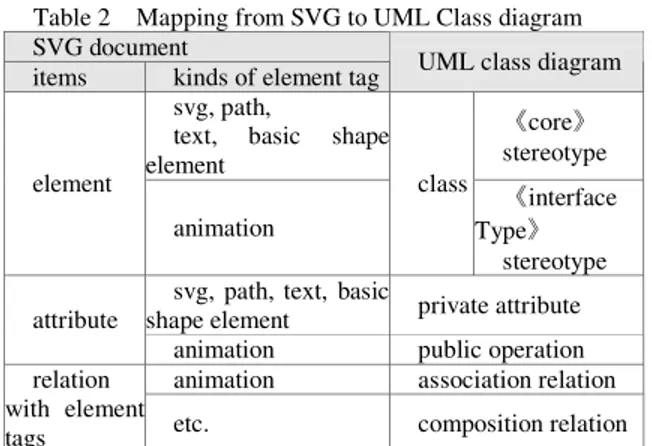
The following table 2 is summarized items in UML class diagram that is mapped to items in SVG Document.
4.1.3 Generating of Interface Type Model
The following rules are inserted operations for ‘ 《interface Type》’ class in interface responsibility model .
[Rule 7] Interface manager class generates get(), set() public operation.
[Rule 8] It maps attributes of animation element class into operations.
The following algorithm is to insert operations to interface responsibility model.
━━━━━━━━━━━━━━━━━━━━━━━━━━━ Input: Interface Responsibility Model
Output: Interface Responsibility Model(insert operations) begin
{
for ( 《interface Type》class if (Interface manager) insert get(), set() operations else { for(number of attributes) map to operation } } end; ━━━━━━━━━━━━━━━━━━━━━━━━━━━ We complete interface responsibility model to insert operation into class in class diagram.
4.1.4 Generating of Component Architecture model It converts interface responsibility model that is UML class diagram into component diagram by using following rules.
[Rule 9] Class with ‘《core》’stereotype is to be a component with ‘《componentSpecification》’stereotype.
[Rule 10] Class with ‘《interface Type》’stereotype is to be interface.
[Rule 11] It is dependency relations between is ‘《componentSpecification》’component. And it is realization relations between component and interface.
The following algorithm generates component diagram by using above rules.
━━━━━━━━━━━━━━━━━━━━━━━━━━━ Input: Interface Responsibility Model
Output: Component Diagram begin
{
for ( 《core》class)
generate 《componentSpecification》component for (《interface Type)class)
generate an interface
for (relations whith《core》classes) make dependency
for( relations with 《core》class and 《interface Type)class)
make a realization relation }
end;
━━━━━━━━━━━━━━━━━━━━━━━━━━━ In the Table 4, we shall describe mapping relations between class diagram and component diagram.
A component represents a modular, deployable, and replaceable part of a system that encapsulates implementation and exposes a set of interfaces. A component is drawn as a rectangle with two smaller rectangles protruding from its left side.
4.2 Results
It generates a component diagram from a SVG documents. 4.2.1 SVG Document
It is an instance of SVG document that is input for this system. ━━━━━━━━━━━━━━━━━━━━━━━━━━━ <?xml version="1.0" standalone="no"?> <!DOCTYPE svg PUBLIC "-//W3C//DTD SVG 20000303 Stylable//EN" "http://www.w3.org/TR/2000/03/ WD-SVG-20000303/DTD/svg-20000303-stylable.dtd"> <svg width="5cm" height="3cm" viewBox="0 0 500 300">
<desc>Example animMotion01 - demonstrate motion animation computations</desc>
<!--Draw the outline of the motion path in blue, along with three small circles at the start, middle and end.-->
<path d="M100,250 C 100,50 400,50 400,250" Table 2 Mapping from SVG to UML Class diagram
SVG document
items kinds of element tag UML class diagram svg, path,
text, basic shape element 《core》 stereotype element animation class 《interface Type》 stereotype svg, path, text, basic
shape element private attribute attribute
animation public operation animation association relation relation
with element
tags etc. composition relation
Table 4 Mapping from UML class diagram to component UML class diagram
item type UML Component Diagram 《core》 stereotype 《componentSpecification》 stereotype component class 《interfaceType》s tereotype interface between 《core》classes dependency relations between《core 》and《interface Type》 realization
style="fill:none; stroke:blue; stroke-width:7.06" /> <circle cx="100" cy="250" r="17.64" style="fill:blue" /> <circle cx="250" cy="100" r="17.64" style="fill:blue" /> <circle cx="400" cy="250" r="17.64" style="fill:blue" /> <!-- Here is a triangle which will be moved about the motion path. It is defined with an upright orientation with the base of the triangle centered horizontally just above the origin. -->
<p ath d="M-25,12.5 L25,12.5 L 0,87.5 z"
style="fill:yellow; stroke:red; stroke-width:7.06" > <!-- Define the motion path animation --> <animateMotion dur="6s" repeatCount="indefinite" path="M100,250 C 100,50 400,50 400,250" rotate="auto" />
</path> </svg>
━━━━━━━━━━━━━━━━━━━━━━━━━
4.2.2 UML Class Diagram
We generates from SVG document to UML class diagram and component diagram.
(1) Business Type model
It generates UML class diagram that is identified core business class defined relationships from SVG document.
Fig 2 Business Type Model (2) Interface Responsibility model
It inserts interface type class to business type model.
Fig 3 Interface Responsibility Model (3) Interface Type Model
It defines interface type model for ‘《interface Type》’class in interface responsibility model.
Fig 4 Interface Type Model
4.2.3 UML Component Diagram
It is component diagram mapped to interface responsibility.
Fig 5 Component Diagram 4.4 Comparison
The following table is comparison of modeling rules with XML application.
XOMT proposes new notations extended OMT. [5,6,7] Modeling interprets XML document structure using static diagram. It accord object-oriented concept( Inheritance etc)
[8, 9] modeling uses synchronized modeling for multimedia document. It is focused on time. This study uses component and interface for modelling web animation.
Main contribution of most study is that it maps XML application to an UML class diagram. But the UML class diagram is focused on static structure for representing XML documents. We can not describe dynamic animations of SVG document using class diagram. This study separates static shape elements and dynamic animation elements. And it uses interface class for supporting animation.
It uses component based development method for generating component diagram. There are 4 steps : the generation of business type model, the generation of interface
responsibility, the generation of interface type and the generation of component architecture.
Table 3 Comparison with modeling of XML applications XOMT [5, 6, 7]
Modeling
[8, 9]
Modeling This study
Domain SGML DTD SGML/XML DTD, document instance (included RDF, WIDL, CDF, OSD) SMIL document SVG document (SMIL animation) Approach Object- Oriented Object- Oriented Object- Oriented Component- based Based modeling language
OMT UML UML UML
Diagram class class, component use case, sequence, collaboration, class, component class, component
Interface none none none
animation element, core class Tool XOMT Editor Rational Rose, Plastic etc Rational Rose, Plastic etc Rational Rose, Together etc 5. Conclusion and future works
This paper proposes an component based development for web animation of SMIL, SVG animation. We need new method to support both static elements and dynamic elements. Main contribution of this paper is that it can make it easier to map SVG component to the object-oriented database scheme due to CBD methods. The CBD tools - Rational Rose or Together etc. - which supports various diagram including component diagrams and makes all kinds of database codes and object-oriented codes.
Research keeps studying how to integrate various XML application for web animation into component diagram and to manage using CBD methods.
REFERENCES
[1] "Scalable Vector Graphics (SVG) 1.0 Specification" http://www.w3.org/TR/2000/03/ WD-SVG-20000303/. [2] Paul Festa, "W3C, 새로운 그래픽 기술 표준 공시“,
http://cnetkorea.co.kr/news/2000/08/03/20000803f.html [3] 권오천, 신규상, “CBD 지원 도구의 핵심 기능”,
정보처리학회지 제 7 권 4 호, pp.18-26.
[4] Inho Park, Ehno Han, Eunju Chong, Eunjung Kim, Jongmin Bae, Hyunsok Kang, Wansyug Kim, "XOMT: An Object Diagramming Technique fir SGML DTD Design, " Journal(C) of KISS, Volume 3, Number 3, pp. 228-237 , 1997.
[5] Yan Ha, Yong Ju Hwang, yong Sung Kim, " Mapping algorithm from SGML DTD to UML class diagram", Journal of KISS(B), Volume 26, Number 4, pp. 508-520, 1999.
[6] Won Seok Chae, Yan Ha, Yong Sung Kim, "XML document structure diagram using UML class diagram",
Journal of KIPs, Volume 6 Number 10, pp. 2670-2679, 1999.
[7] Mi Kyung Lee, Yan Ha, Yong Sung Kim, "Convert from RDF schema to UML Class Diagram", Journal of KIPs, Volume 7, Number 1, pp. 29-40, 2000.
[8] Won Seok Chae, Yan Ha, Yong Sung Kim, "Synchronization of SMIL Document using UML use case and sequence diagram", Journal of KISS(Software applications), Volume 27, Number 4, pp.357-369, 2000. [9] Sang-eun Kim, Yan ha, Yong-sung Kim, “ Integrated object modelling of SMIL, RDF, and WIDL document.”, Journal of KISS(software and application), Volume 28, Number 1, 2001.
[10] "SMIL Animation", http://www.w3c.org/TR/smil-animation/.
[11] James Rumbaugh, Ivar Jacobson, Grady Booch, "The unified modeling language reference manual", Addison Wesley Longman Inc., 1999.
[12] "OMG Unified Modeling Language Specification Version1.3", http://www.rational.com/media/uml/ post.pdf, 1999. 6.
[13] Cool Software Korea, "CBD Training using COOL:Joe 1.1", 2000. 10.
[14] Natanya Pitts-Moultis, Cheryl Kirk, "XML Black Book", The Coriolis Group Inc., 1999.
[15] Elliotte Rusty Harold 저, 김용권 역, "XML Bible", 정보문화사, 1999.
![Table 3 Comparison with modeling of XML applications XOMT [5, 6, 7]](https://thumb-ap.123doks.com/thumbv2/123dokinfo/4891562.37087/6.918.113.443.188.569/table-comparison-modeling-xml-applications-xomt.webp)
