49-3 / L. Herbst
• IMID 2009 DIGEST
Advances in excimer laser annealing for LTPS manufacturing
Ludolf Herbst
1, Frank Simon
1, Rainer Paetzel
1,
Suk-Hwan Chung
2, and Junichi Shida
21
Coherent GmbH, Hans-Boeckler-Strasse 12, 37079 Goettingen, Germany
TEL:+49-551-69380, e-mail: ludolf.herbst@coherent.com
2
The Japan Steel Works, Ltd., 2-2-1, Fukuura Kanazawa-Ku, Yokohama 236-0004, Japan
Keywords: LTPS, Excimer Laser Annealing, AMOLED
Abstract
Several different production technologies for
Low-Temperature Poly-Silicon (LTPS) have been
proposed over the last years. However, finally the progress in Excimer-laser-based crystallization has lead to the best cost-to-performance ratio of LTPS manufacturing for use in active-matrix-based displays. In this paper, we report on recent and significant technical advances in light sources, optical beam deliveries and beam irradiation systems targeted at enabling ultra-uniform mura-free LTPS active-matrix backplanes while simultaneously lowering production costs and increasing throughput.
1. Introduction
Low temperature polycrystalline silicon (LTPS) is utilized as the active material for thin-film transistor (TFT) devices in small and medium sized flat panel displays in case the performance characteristics such as electron mobility and TFT output current stability offered by amorphous-Si is insufficient [1]. For active-matrix liquid-crystal displays (AMLCDs), LTPS provides higher resolution and higher brightness capability, and it enables circuit integration directly into the display panel, paving the way for lowered manufacturing costs and advanced System On Glass (SOG) applications. LTPS based TFT arrays as backplanes for active-matrix organic light-emitting diode displays (AMOLEDs) are commonly accepted because LTPS based TFTs support much higher current than amorphous-Si TFTs, which is essential for the current driven organic diodes [1]. However, the requirements set by the AMOLED are a very high with respect to TFT threshold voltage uniformity and, therefore, an extremely high degree of crystallization uniformity is demanded.
With increasing demand for LTPS backplanes several different Si thin film crystallization techniques like solid-phase crystallization (SPC) and green laser annealing where proposed [2]. However, further progress in the most widely adopted excimer laser crystallization technique for LTPS has made it the only production proven quality process for high quantity LTPS production for high performance displays. In order to make excimer laser crystallization more attractive in AMLCD production and to demonstrate its capability to satisfy the extreme demands of AMOLED production, we have placed significant efforts on improving the performance of the laser, the optics and the annealing system, which has lead to better process control. This in turn enables high productivity crystallization systems for especially AMOLED applications. Based on a significant amount of optimization of both, laser and optics, the excimer annealing system has been successfully implemented in the mass-production of small AMOLED displays for mobile applications.
2. ELA systems
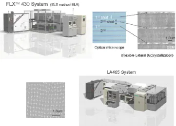
As mentioned above, a high degree of crystallization uniformity is essential for AMOLED backplanes. Hence, the requirements for AMOLED ELA systems compared to conventional models are very high. There are two types of ELA systems available which are distinguished by the annealing technique: the SLS (Sequential Lateral Solidification) method and the partial melt method. Both types shown in Fig. 1 consist of laser, optics and annealing system.[4] The lasers are common but the optical configuration and the annealing systems are different for each type.
49-3 / L. Herbst
IMID 2009 DIGEST •
Fig. 1. FLXTM 430 System (SLS 2D-projection
ELA) and LA465 System (Partial Melt Line-Beam ELA)
3. Mura countermeasure for SLS methods
The JSW (Japan Steel Works) FLXTM series ELA
system uses the SLS method for the crystallization. In the SLS method complete melting of the thin silicon film is used. Therefore, the crystallization has a large process window and is less influenced by a change of the laser energy. However, some variation of the crystals occurs by the following items.
・ Focus position variation of projection lens ・ Beam size change
・ Accuracy of precision X-Y-Z stage ・ Flatness of glass sheet and chuck ・ Vibration of the ELA system
In order to overcome the mentioned limitations and to achieve mura free LTPS, the following technologies have been introduced. To provide highest degree of homogeneity on the substrate a new projection lens was designed to operate with minimal distortion at higher power. The new projection lens enables the 600 Hz repetition rate laser, with 540 W output power, to be directly implemented in the high-throughput crystallization system. As the 2D-projection SLS technology is not fundamentally limited in terms of scalability, the added process speed will significantly benefit systems considering mother glass sizes larger than the current Gen. 4 standard.
One relevant source for defocus of the system is the inherent limited flatness of glass and chuck. The large area surface flatness variation of the glass sheet on the chuck is more than 30µm at glass size of Gen. 4 (730x920mm²). This variation is in the range of the projection lens depth of focus (DOF) which is 35 – 40µm. Crystallization in the center focus position
gives best results and small defocusing may already lead to mura effects. Therefore the FLX series ELA system incorporates an “Auto Focus Control (AFC)” which is essential to achieve uniform poly-Si crystals without defect in the full area of Gen. 4 and larger glass. The AFC can keep the distance between the projection lens and the glass surface constant. Fig. 2 shows the AFC error; the measured AFC errors are within ± 3µm during full Gen. 4 glass irradiation at a stage velocity of 300mm/sec.
Fig. 2. AFC error histogram during full area crystallization of Gen. 4 size glass.
The JSW FLXTM series ELA system irradiates the
silicon film at energy densities of more than 700mJ/cm² to completely melt the silicon. During
continuous irradiation, the focal distance of the projection lens is influenced by the total applied laser power. For that reason the system utilizes a projection lens shutter, which will block the laser during panel exchange. The projection lens shutter utilizes a mirror which reflects the laser beam at a similar rate as the amorphous silicon film. Thus, the projection lens shutter maintains the focal position constant during the exchange of glass substrates after crystallization.[5] As a result, the focus errors of each glass irradiation are much below +/- 10µm. Fig. 3 shows the focus error of seven consecutive annealed glass substrates. 2000 2100 2200 2300 2400 2500 2600 2700 2800 2900 3000 3100 3200 3300 3400 3500 -10-8 -6 -4 -20 2 4 6 8 10 Time (sec) Er ror ( µ m)
Fig. 3. Focus error of seven consecutive annealed glass substrates
49-3 / L. Herbst
• IMID 2009 DIGEST
4. Mura countermeasure for
partial melt method
(Line beam ELA system)
By further improving excimer laser technology, Coherent has been able to achieve high pulse energy and beam stability from lasers operating at 308 nm. Furthermore, in order to increase the annealing throughput the laser repetition rate was increased from 300 to 600 Hz. With providing 1000 mJ pulse energy there are up to 600 W available. Compared to previous maximum output powers of 315 W it means almost doubled output power. The peak-to-peak energy stability of the high power laser version is shown in Fig. 4; the histogram is based on a test run over 62 million laser pulses. More than 99.999% of laser pulses are within the target energy window of +/-1.5%. This stability is maintained under production conditions, over a 2 day working period to enable the uninterrupted production of the annealing system. In view of the application, which is sensitive to the exact energy of a single laser pulse, the achievement of this very tight energy distribution is one of the key requirements to reach a high yield.
1,0E+00 1,0E+01 1,0E+02 1,0E+03 1,0E+04 1,0E+05 1,0E+06 1,0E+07 1,0E+08 105,50 104,50 103,50 102,50 101,50 100,50 99,50 98,50 97,50 96,50 95,50 94,50 rel. energy / % oc cu rr en ce / lo g. s ca le 3% p2p energy stability 99.999% of laser pulses 62 Mpulses in histogram
Fig. 4. Data collected from LAMBDA SX laser demonstrating high peak-to-peak energy stability at 600 Hz operation.
This high degree of pulse energy stability is essential in order to produce very uniform LTPS film by the laser partial melt crystallization process.
Coherent’s beam delivery systems have also made significant advancements recently. ELA systems have demonstrated the capability of forming highly-uniform mura-free backplanes especially suitable for AMOLED products. This was found to be possible only by the use of advanced optical schemes and system level optimization.
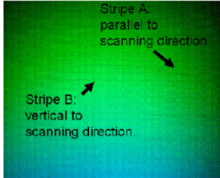
The partial melt Line-Beam method is the widely used and most mature LTPS technology. Although the crystal grain size is small the grain form is very isotropic and as a result the TFT design is flexible. However, also in this method specific mura effects have occurred which have now been eliminated by technical countermeasures. Typical mura effects are shown in Fig. 5.
Fig. 5. Mura in the line beam ELA system.
There are two types of mura. One is parallel to the laser beam scanning direction (Stripe A). The other is vertical to the laser beam scanning direction (Stripe B). Stripe A may be caused by very slight in-homogeneity within the line beam optics system, leading to a distinct non-uniformity of the line beam intensity profile. As a countermeasure we developed the “Micro-Smoothing” technology, which actively controls the position of the non-uniformity randomly. As a result stripe A becomes weaker and the mura effect is much reduced. (Fig. 6)[6]
Fig. 6. Effect of Micro-smoothing
The reasons of the mura represented by stripe B are attributed to stage velocity fluctuations, vibrations of the system, beam position instability for short axis and laser pulse energy fluctuations. The LineBeam ELA system was improved in regard to stage velocity
49-3 / L. Herbst
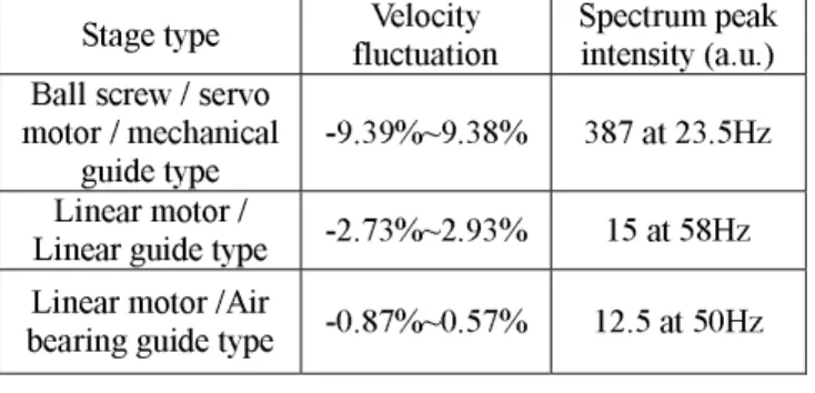
IMID 2009 DIGEST • stability in order to avoid stripe B type mura. Table 1
shows the comparison of each stage type performance. When the X-Y-stage is scanned to achieve an overlap of i.e. 95% of the beam width (400 µm), the total laser shots number at each position is 20.Depending on the stage velocity precision the irradiation shot numbers will vary. For example a ball screw / servo motor / mechanical guide type stage may lead to fluctuation of the irradiation between 18.3 shots to 22.1 shots. A linear motor / air bearing guide type stage is much more accurate and as a result the fluctuation of the irradiation is limited to only 19.9 shots to 20.2 shots. As a result a linear motor / air bearing guide type stage is able to reduce velocity fluctuation approximately 10 times than ball screw type.
Table 1. Comparison of stage velocity fluctuation and its spectrum peak
Stage type fluctuation Velocity Spectrum peak intensity (a.u.) Ball screw / servo
motor / mechanical
guide type -9.39%~9.38% 387 at 23.5Hz
Linear motor /
Linear guide type -2.73%~2.93% 15 at 58Hz
Linear motor /Air
bearing guide type -0.87%~0.57% 12.5 at 50Hz
5. Outlook
The ongoing trend of enlarging glass sheet size requires further improvements and up scaling of the ELA production system capabilities. Therefore increasing laser output power as well as the illumination area of the LineBeam optics is ongoing in order to meet ambitious throughput and cost goals set
by display manufacturers. High power laser, ultra-flat glass sheet chuck and high precision stage for Gen. 5 AMOLED substrates are becoming available already.
6. Summary
The advancement of excimer laser technology, beam delivery optics and annealing systems directly impacts the LTPS market and its competitiveness. By optimizing the various system performance characteristics, we are able to demonstrate uniform mura-free backplanes which are enabling the mass production of AMOLED products. The introduction of a new high power laser, a distortion free projection lens, AFC, Micro-smoothing and Temperature control for the projection lens also increase the reliability, productivity and throughput of both partial melt and SLS technologies.
7. References
[1] J.-J. Lih et. al., Journal of the SID 12/4, p367,
2004
[2] R.Kawakami et. al., IDMC 07 proceedings, p721,
2007
[3] R. Paetzel, J. Brune, L. Herbst, F. Simon, ITC09 International proceedings, p, 2009
[4] K. Funaba, J. Shida, JSW Technical review No.19,
p78, 2008
[5] J. Shida, Laser irradiation method and its system, Japan Patent no. 3845650 (2006)
[6] S.Kanazawa, Laser irradiation method and its system, Japan Patent no. 4297923 (2006)