The Effects of the Shear keys and ICI penetrations on the Two-Phase Natural Circulation Flow
Kwang-Soon Haa, Ji-Yong ChoiaRae-Joon Parka,Sang-Baik Kima, andKwang-Yong Kimba Thermal-Hydraulic Safety Research Division, Korea Atomic Energy Research Institute 150 Deokjin-dong, Yuseong-gu, Daejeon, 305-353, tomo@kaeri.re.kr
b Inha Univ., Mechanical Eng. Dept., 253 Yong-Hyun Dong, Nam-Gu, Incheon, 402-751
1. Introduction
To observe and evaluate the two-phase natural circulation phenomena through the gap between the reactor vessel and the insulation in the APR1400 under the external vessel cooling, the T-HERMES (Thermo-Hydraulic Evaluations of Reactor vessel cooling Mechanisms by External Self-induced flow) program has been performed in KAERI [1,2]. The HERMES-HALF study [2], which is one of the T-HERMES programs, is a non-heating experimental study on the two-phase natural circulation through the annular gap between the reactor vessel and the insulation. By the HERMES-HALF experimental study, the natural circulation mass flow rates have been measured experimentally with variations of the injected air flow rate, water inlet area / configurations and outlet area, and simple empirical correlations to predict the circulation mass flow rates were obtained from the experimental results.
In the present research, the HERMES-HALF experiments were simulated numerically to analyze the effect of the shear keys and ICI penetrations on the void fractions and the natural circulation mass flow rate of cooling water in nuclear cavity.
2. Methods
CFX-5.7 was used as a numerical analysis tools to solve the unsteady, three-dimensional Reynolds averaged Navier-Stokes equations for multi phase flow with zero equation turbulence model.
2.1 Governing Equations Continuity equation
(
)
+∇⋅(
)
=0 ∂ ∂ α α α α αρ γ ρ γ U t r Momentum equation(
γαραUα)
(
γα(
ραUα Uα)
)
t r r r ⊗ ⋅ ∇ + ∂ ∂(
α)
α α α α α α γ µ γ P U U T M r r r + ∇ +∇ ⋅ ∇ + ∇ − =Volume conservation equation
∑
= = P N 1 1 α α γwhere, α represents phase, γ is void fraction of each phase and Np means number of phases.
The complete set of hydrodynamic equations represent 4Np+1 equations in the 5Np unknowns, Uα, Vα, Wα, γα, Pα.
We need Np-1 more equations to close the system. These
are given by constraints on the pressure, namely that all phases share the same pressure field
1, , p
Pα=P for all α= LLN
Interphase momentum transfer, Mα
r , can be written as follows
(
)
D d Mαβ =cαβ Uβ−Uα r r r , 3 , 4 8 d D D p C C c r U U or A U U d αβ= βρα β− α = αβρα β− α r r r rwhere, Aαβ is an interfacial area between phase α and β.
In the present calculation, Grace drag model was adopted to model the drag coefficient.
2.2 Grid System and Boundary Conditions
To increase the grid quality, the overall grid system is generated circumspectly using ICEM CFD 4.0 which can handle the complex geometry.
Considering the symmetry of the geometry, half region is considered. Four different air velocities are set at the hemisphere of the vessel as inlet boundary conditions to simulate the corresponding amount of steam generation under severe accident. The details of the geometrical conditions are the same as those of the HERMES-HALF experimental facility [2]. Opening condition is used for air ventilation. No slip condition for water and slip condition for air are set at all walls.
2.3 Calculation Strategy
Injected air diameter is 0.005m and surface tension between air and water was set as 0.0725 N/m. Initial water level is 1.5m below from the top of the vessel. Cavity and Transactions of the Korean Nuclear Society Autumn Meeting
water pool are filled with the stationary water initially. Total calculation time is 10 seconds after the air injection and time step is set as 0.05 second. Parallel computation was implemented using 5 Pentium IV 2.4 GHz PC and 72 hours were required to complete the calculation.
3. Results
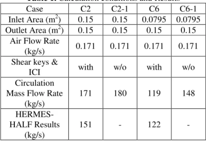
In Table 1, the calculation conditions and results are summarized. Two outlets located at 45 and 135 degrees of longitude on the annular section of the reactor vessel wall are opened. The each outlet has a rectangular shape (0.2×0.375m), and the height from the bottom of the reactor vessel to the center of the outlet port is 3.384m. The bottom inlet holes are located on the circumferential parts in the lower insulation section. The injected air mass flow rate is 0.171kg/s. The inlet area is 0.15m2 (case C2) and 0.0795m2 (Case C6). The C2-1 and C6-1 are the cases of no shear keys and ICI penetrations.
The calculated circulation mass flow rates coincide with the HERMES-HALF experimental data within 13% error bounds. Table 1 shows that the circulation mass flow rates decrease if the shear keys and ICI penetrations are inserted into the flow path. So, the shear keys and ICI penetrations have negative effects on the natural circulation mass flow.
Table 1. Calculation conditions and Results
Case C2 C2-1 C6 C6-1
Inlet Area (m2) 0.15 0.15 0.0795 0.0795 Outlet Area (m2) 0.15 0.15 0.15 0.15
Air Flow Rate
(kg/s) 0.171 0.171 0.171 0.171 Shear keys &
ICI with w/o with w/o
Circulation Mass Flow Rate
(kg/s) 171 180 119 148 HERMES-HALF Results (kg/s) 151 - 122 -
Figure 1 represents the void fraction distribution near the shear key regions of case C6 and C6-1. If the shear keys exist in case of C6-1, sudden increase of the void fraction occurs due to the flow separation around the shear key. It is thought that this flow separation is one factor of the natural circulation flow decrease.
4. Conclusion
Three-dimensional, unsteady and multi-phase natural flow was simulated to analyze the flow characteristics to evaluate the effect of the shear keys and ICI penetrations
on the natural circulation mass flow rates between the reactor vessel and the insulation under the external reactor vessel cooling condition. From the results, the shear keys and ICI penetrations have negative effects on the natural circulation mass flow.
By extending the present numerical analysis, shear key and ICI nozzle effects on natural flow characteristics should be evaluated quantitatively.
Acknowledgments
This study has been performed under the Long-and-Mid-Term Nuclear R&D Program supported by Ministry of Science and Technology, Republic of Korea
References
[1] K. S. Ha, R. J. Park, H. Y. Kim, S. B. Kim, and H. D. Kim, A Study on the Two-Phase Natural Circulation Flow through the Annular Gap between a Reactor Vessel and Insulation System, Int. Comm. in Heat and Mass Transfer, Vol. 31, No. 1, pp.43-52, 2004.
[2] K. S. Ha, R. J. Park, Y. R. Cho, S. B. Kim, and H. D. Kim, An Experimental Study on the Two-Phase Natural Circulation Flow under ERVC, 2005 KNS Spring Meeting, May, 2005.
(a) Case C6
(b) Case C6-1
Figure 1. Void faction distribution near the shear key region