1. INTRODUCTION
Recently, the problems for establishing interaction between the robot and humans become increasingly important as robots have been deployed into our daily life. Particularly, in the remote control of mobile robots such as service robots in our everyday environment, an easy-to-use human interface is required that helps the ordinary user easily understand the context of the remote environment. Among various types of interface technologies available, the vision-based interface has been the most widely employed. However, it only provides geometric features of the environment onto 2D display systems that often makes the user difficult to recognize the precise positions of the objects and the state of the robot itself. Therefore, it is necessary to augment virtual 3D information to the 2D visual feedback display and provide the remote operator with object-related information such as locations, shape, size, material properties, and so on.
In order to augment the 3D information to the human interface, many researchers have so far developed 3D object construction methods mainly using stereo vision systems, panoramic cameras, and various sensors. Almost all of those approaches generate 3D object and environment with a single point of view, or have to explore the object and the environment in advance. They are inefficient and costly when building 3D maps of unknown environments. In this paper, therefore, we propose a vision-based human interface system that provides an interactive, information-rich 3D map, incorporating an object recognition part, a 3D map construction part, a networked knowledge base part, and a control part of the mobile robot.
Specifically, the object recognition part acquires the visual feedback image and estimates the spatial position of the perceived object by panning and tilting the stereo vision camera. Then, the 3D model of the object is constructed simultaneously in the separated extra window display in a controllable manner. Moreover, using the information brokering through the World Wide Web (WWW) server, the object-related information can be linked to the virtual 3D map that interactively provides details of object information if requested. To evaluate the proposed human interface system having the dual window display, we apply the developed system to the teleopration of the mobile robot in an office environment. Details of the system development and preliminary experimental results are described in this paper.
2. SYSTEM DEVELOPMENT
2.1 System outlineThe schematic of the proposed system is shown in Fig. 1. T he system consists of a robot server, a user client, and a WW W server, all connected to the network. The robot server has the following parts: an object recognition part, a 3D object construction part, and a mobile robot control part. The client provides the information-rich 3D map and joys tick interface for intuitive human interface. The WWW se rver is a networked knowledge base to provide detailed i nformation of the object to the server and client.
RS-23
2
Fig. 1 System outline
2.2 Experimental setup
We use a set of two digital camera systems (Flea, PGR Inc.), each of which has the IEEE 1394 interface. This small size, high resolution (640×480 color) camera does not require the frame grabber device. Both camera are mounted onto the pan and tilt positioner (PTU-D-46, Directed Perception Inc.) whose controller is connected to the robot server through a serial communication. The camera system equipped with the positioner is then installed on the mobile robot (Pioneer 3, ActivMedia Robotics) which is controlled by a joystick on the network. For information brokering, we build a web server as the knowledge base that contains information related to the object. The transmission of the object information between the server and the client is designed as a packet structure of C++. Fig. 2 is a snapshot of the mobile robot with the camera system and the notebook PC-based robot server.
Building Information-rich Maps for Intuitive Human Interface Using
Networked Knowledge Base
Jae-Kwan Ryu, Chie Kanayama, and Nak Young Chong
School of Information Science, Japan Advanced Institute of Science and Technology, Ishikawa 923-1292, JAPAN (Tel : +81-761-51-1248; E-mail: [email protected] )
Abstract: Despite significant advances in multimedia transferring technologies in various fields of robotics, it is sometimes quite
difficult for the operator to fully understand the context of 3D remote environments from 2D image feedback. Particularly, in the remote control of mobile robots, the recognition of the object associated with the task is very important, because the operator has to control the robot safely in various situations not through trial and error. Therefore, it is necessary to provide the operator with 3D volumetric models of the object and object-related information as well such as locations, shape, size, material properties, and so on. Thus, in this paper, we propose a vision-based human interface system that provides an interactive, information-rich map through network-based information brokering. The system consists of an object recognition part, a 3D map building part, a networked knowledge base part, and a control part of the mobile robot.
Fig. 2 Snapshot of proposed robot system
2.3 Image matching
To recognize the object, we employ a simple image matching algorithm. For securing the efficiency of the matching process, we have four stages to preprocess the feedback image. The preprocessing steps are conversion of color images to monochrome, edge detection, binary image construction, and image scaling down, respectively. The preprocessing removes the noise of the image and simplifies the overall operation. To enable the image matching in real time, in addition to the scale down already used in the preprocessing stage, the single-instruction, multi-data (SIMD) technology is also used. SIMD technology is often employed to speed up the processing of multimedia software by handling massive data in parallel. The rotation angle of the object is detected by rotating the reference images pre-stored in the robot sever.
2.4 3D position of object sensing
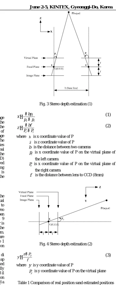
It is necessary to know the exact 3D coordinates of the object to position the object model in the 3D virtual environment. Thus, we developed a stereo vision system to estimate 3D positions of the recognized object. The stereo vision system consists of two cameras equipped with the pan and tilt positioner as shown in Fig. 2. Each camera is 9 centimeters away on the bracket. The pan and tilt positioner is used to search and track the object. Figs. 3 and 4 illustrate the relation of geometry parameters of the stereo vision system. Equations (1) through (3), derived from Figs. 3 and 4, are calculated to estimate the 3D positions of the object. Table 1 shows the results of the estimated positions of the object on the image plane with the actual measured positions.
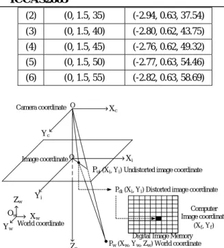
The optical lens systems suffer from nonlinear radial di stortion which should be compensated for image-based ap plications. In this work, the lens distortion is compensated using the relaxed photogrammetry model, where technically the Tsai calibration algorithm is implemented [4], [5]. Fig. 3 il lustrates the camera geometry with the perspective projection and radial lens distortion model. Specifically, we developed a program to find x and y coordinates of the dots of the calibration jig on the image plane using MATLAB Image Processing Toolbox. To precisely calibrate the distortion, we calculated the center points of the dots as sub-pixel unit.
Fig. 3 Stereo depth estimation (1)
l r l p p bp x − − =
(1)
l r P P bf z − − =(2)
where x is x coordinate value of Pz
is z coordinate value of Pb is the distance between two cameras
l
p is x coordinate value of P on the virtual plane of the left camera
r
P is x coordinate value of P on the virtual plane of the right camera
f
is the distance between lens to CCD (8mm)Fig. 4 Stereo depth estimation (2)
f P z
y= − y
(3)
wherey
is y coordinate value of Py
P is y coordinate value of P on the virtual plane Table 1 Comparison of real position sand estimated positions
in Cartesian coordinates (unit: cm) Actual position Estimated position
(2) (0, 1.5, 35) (-2.94, 0.63, 37.54) (3) (0, 1.5, 40) (-2.80, 0.62, 43.75) (4) (0, 1.5, 45) (-2.76, 0.62, 49.32) (5) (0, 1.5, 50) (-2.77, 0.63, 54.46) (6) (0, 1.5, 55) (-2.82, 0.63, 58.69) World coordinate Image coordinate Camera coordinate O O Ow Xc Yc Zc Zw Xw Yw Yi Xi
Pui(Xi, Yi) Undistorted image coordinate
Pdi(Xi, Yi) Distorted image coordinate
Pw(Xw, Yw, Zw) World coordinate Digital Image Memory
Computer Image coordinate
(Xf, Yf)
Fig. 5 Camera geometry with perspective projection and radial lens distortions
2.5 Information linking
The web server allows the user to request information about the object in the virtual environment. We input the URL address of the server into the header of the reference image file. The URL address is the pointer to the information storage location on the network. The information which can be downloaded at the client includes OpenGL data, name, weight, material, and handling information of the object. Using the information and the position data, the system can construct the information-rich virtual environment.
2.6 Mobile robot controlling
The mobile robot is controlled by the user on network through the joystick interface at the client. The joystick commands are transmitted to the robot server as a packet. The robot control part uses the Saphira API to modify the motion set-points in the state reflector.
2.7 3D object data construction
The VRML data of the object is created by SolidWorks and transitioned seamlessly to OpenGL. The 3D OpenGL data is uploaded to the web server. Fig. 6 shows the procedure for uploading models to the WWW server.
Fig. 6 Process of 3D data making
3. HUMAN INTERFACE
3.1 Robot server
The robot server incorporates different modules: the object recognition, Pioneer 3 control, pan and tilt control, and interface with the Saphira. Fig. 7 shows the server window which has the following three interface parts: (1) two windows for each camera, (2) Saphira graphical interface, and (3) camera and pan/tilt control buttons.
Fig. 7 Robot server of the proposed system and Saphira interface
3.2 User client
Fig. 8 shows the snapshot of the client window which has the following three parts: (1) video image window, (2) 3D map window, (3) network control buttons, (4) menu selection buttons, and (5) pan and tilt control buttons. To assist the operator in recognizing intuitively the remote environment, we arranged the positions of the video feedback window and the virtual 3D map window. Because the view point of the 3D map window can be controlled by the mouse, the user easily understands a bird’s eye view and/or a perspective view of the remote environment. Also, through the menu selection buttons, he/she can choose and see the video image data from each camera. Likewise, providing the joystick interface as well, he/she feels confident with a wide variety of the interface.
Fig. 8 User client of the proposed system
4. RESULTS
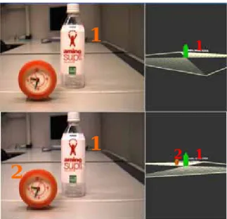
4.1 Simple 3D map constructionIn the preliminary test, from the sample video data of a bottle and a clock, the system generates volumetric models in the 3D map window and displays the supplementary
1
2
3
4
5
1
2
3
information of the objects. The system uses a global coordinate for robot localization [7]. The generated models are located in proportion to the actual distance in the real world. Figs. 9 and 10 show the positioning of the models and multiple points of view. Fig.11 shows the supplementary information attached to the objects.
Fig. 9 Recognizing and positioning of objects
Fig. 10 Control of view point by mouse
Fig. 11 Display of the supplementary information
4.2 Mobile robot application
To verify how the proposed human interface system helps the operator understand the context of the remote environment, we built a remote environment as shown in Fig. 12 for the mobile robot application scenario. We performed a test experiment for the following two interface modes: (1) only with the 2D image feedback, (2) with the 3D map and knowledge of the objects with spatial information. The
operator is requested to perform the same manual operation with both interfaces. The desired robot path is shown in Fig. 12. Fig. 13 shows the dual interface window of case (2) which also provides the heading direction of the robot. The operator has no a priori knowledge about the system and the remote environment. He/she is requested to finish the operation within 5 minutes. The system records the path of the mobile robot and displays it. Fig. 14 shows the path of the mobile robot controlled with the interface of case (1). Almost operators failed and felt difficulty in operating the mobile robot. During the operation, the control command was issued on average 37 times. The red circle indicates the command point for controlling the robot. The dashed line is the actual path of the robot. Fig. 15 is the actual path of the robot controlled with the interface of case (2). The control command was issued on average 18 times during the operation.
Fig. 12 Path assigned to the mobile robot
Fig. 13 2D image feedback and virtual 3D map of the remote environment
Fig. 14 Actual path of the robot trace in case (1)
1
1
2
1
1
2
StartFig. 15 Actual path of the robot in case (2)
5. DISCUSSIONS AND CONCLUSTIONS
Understanding the context of the 3D environment from 2D image feedback is a very difficult problem. Thus, we developed a new vision-based human interface system that provides virtual volumetric object from video data and object-related information onto the display interacting with the networked knowledge base. The system automatically generated 3D maps of the environment proving multiple points of view and supplementary information related to the recognized object for intuitive human interface. The developed system helped the operator easily understand the remote environment and make the decision in controlling the robot.
From the results of the experiment in this work, we noticed that the number of control commands decreased dramatically due to the interactive, information-rich virtual environment. It is expected that the proposed interface system can be applied to a wide variety of mobile robot teleoperation in indoor environments.
ACKNOWLEDGMENTS
This research is conducted as a program for the "Fostering Talent in Emergent Research Fields" in Special Coordination Funds for Promoting Science and Technology by Ministry of Education, Culture, Sports, Science and Technology of Japan. We would also like to thank Mr. Geunho Lee for his helpful advice in the control of Pioneer 3.
REFERENCES
[1] N.Y. Chong, H. Hongu, K. Ohba, S. Hirai, K. Tanie, “Knowledge distributed robot control framework,” Proc. Int. Conf. on Control, Automation, and Systems, 2003. [2] H.S. Kim, K.H. Sohn, “3D reconstruction from stereo
images for interaction between real and virtual objects,” Image Communication, 2004.
[3] P. Dunias, N.G.M. Kouwenberg, “Knowledge-based 3-D object recognition,” IEEE IMTC, 1994.
[4] R. Y. Tsai, “A versatile camera calibration technique for high accuracy 3D machine vision metrology using off- the-shelf TV camera and lenses,” IEEE Journal of
Robotics and Automation, Vol. 3, no. 4, pp. 323-344, 1987.
[5] J. Weng, P. Chohen, M. Herniou, “Camera calibration with distortion models and accuracy evaluation,” IEEE Transactions on Pattern Analysis and Machine Intellience, Vol. 14, No. 10, pp. 965-980, 1992.
[6] G. Borgefors, “Distance transformation in digital images,” Computer Vision, Graphics, and Image Processing, Vol. 34, pp. 344-371, 1986.
[7] E. M. Mouaddib, B. Marhic, “Geometrical matching for mobile robot localization,” IEEE Transaction on Robotic and Automation, Vol. 16, No. 6, 2000.
[8] Reimar K. Lenz, R.Y. Tsai, “Techniques for calibration of the scale factor and image center for high accuracy 3-D machine vision metrology,” IEEE Transaction on pattern analysis and machine intelligence, Vol. 10, No. 5, pp. 713-720, 1988.