저작자표시-비영리-변경금지 2.0 대한민국 이용자는 아래의 조건을 따르는 경우에 한하여 자유롭게 l 이 저작물을 복제, 배포, 전송, 전시, 공연 및 방송할 수 있습니다. 다음과 같은 조건을 따라야 합니다: l 귀하는, 이 저작물의 재이용이나 배포의 경우, 이 저작물에 적용된 이용허락조건 을 명확하게 나타내어야 합니다. l 저작권자로부터 별도의 허가를 받으면 이러한 조건들은 적용되지 않습니다. 저작권법에 따른 이용자의 권리는 위의 내용에 의하여 영향을 받지 않습니다. 이것은 이용허락규약(Legal Code)을 이해하기 쉽게 요약한 것입니다. Disclaimer 저작자표시. 귀하는 원저작자를 표시하여야 합니다. 비영리. 귀하는 이 저작물을 영리 목적으로 이용할 수 없습니다. 변경금지. 귀하는 이 저작물을 개작, 변형 또는 가공할 수 없습니다.
A Study to Evaluate the Structural Integrity of the
Plate Type Heat Exchanger using FEM Analysis
본 논문을 이승민의 공학석사 학위논문으로 인준함.
위원장
박 권 하
위
원
방 광 현
)
위
원
조 종 래
년
월
일
2013
02
01
한국해양대학교 대학원
Abstract ··· i
Nomenclature ··· ii
List of Tables ··· iii
List of Figures ··· iv 1. 1.1 ··· 1 1.2 ··· 2 1.3 ··· 3 2. 2.1 ··· 4 2.2 ··· 6 2.3 ··· 9 3. 3.1 ··· 11 3.2 ··· 13 3.3 ··· 18 4. 4.1 ··· 20 4.1.1 ··· 20 4.1.2 ··· 23 4.2 ··· 26
4.2.2 ··· 30 4.2.3 ··· 31 5. 5.1 ··· 40 5.1.1 ··· 45 5.2 ··· 47 5.2.1 ··· 47 5.2.2 ··· 53 6. 6.1 ··· 58 6.1.1 ··· 58 6.2 ··· 60 6.2.1 ··· 61 7. ··· 66 APPENDIX A ··· 67
A Study to Evaluate the Structural Integrity of the
Plate Type Heat Exchanger using FEM Analysis
Seung-Min Lee
Department of Mechanical Engineering, Graduate School,
Korea Maritime University
The purpose of this study is to evaluate a structural integrity of plate type heat exchanger considering the behavior of the global structure and is to perform finite element analysis and code calculation as the way to verify the structural integrity. Recently, the research on plate type heat exchanger has been focused on performance improvement considering the shape and size, however, this study is going to establish the criteria for the supporting structure of the plate type heat exchanger integrity.
Structures under internal pressure flat plate, fixed frame and maximum bolt load were evaluated a structural integrity by performing code calculation The advantages of the plate type heat exchanger is that it is easy to assemble and disassemble, which is up to 1.5 times the actual weight of the evaluation of the structural integrity in carrying bar of body part. The allowable bending stress of the beam type structures which carrying bar and support column is applied to 0.66Sy and flat type like a base plate is applied to 0.6Sy. In addition, the maximum deformation allows 6 inch per 100ft.
In this study, the pre-processing module using Visual Basic and ANSYS APDL has been proposed to save time in FE modeling and analysis to improve an accuracy.
Nomenclature
{}
{}
{}
{}
{}
탄성 계수 : (Young's modulus) 질량 행렬 : (mass matrix) 감쇠 행렬 : (damping matrix) 강성 행렬 : (stiffness matrix) 최대 변위 : (maximum displacement) 선팽창계수: (mean linear expansion, ㎛ ㎛/ K) 인장 변형률
: (tensile strain) 의 제곱근
: -1 (square root of -1) 주파수
: (imposed frequency, cycle/time) 진동수
: (imposed circular frequency, radians/time) 인장 응력 : (tensile stress) 포아송비 : (Poisson's ratio) 전단 변형률 : (shearing strain) 전단 응력 : (shearing stress) 변위 위상각
: (displacement phase shift, radians) 가진 위상각
: (force phase shift, radians) 절점의 변위 벡터
: (nodal displacement vector)
절점의 속도 벡터
: (nodal velocity vector)
절점의 가속도 벡터
: (nodal acceleration vector)
작용하중 벡터
: (applied load vector)
자유진동 모드행렬 :
List of Tables
Table 1 Design pressure and temperature Table 2 Dead load
Table 3 Nozzle load
Table 4 Hydrostatic test pressure Table 5 Wind load
Table 6 Seismic load Table 7 Material summary
Table 8 Allowable limit for Fixed frame Table 9 Frame design input data
Table 10 Anchor bolt design input data Table 11 Tension and shear stress check Table 12 Analysis case
Table 13 Analysis results for each components Table 14 Analysis results for fixed frame
Table 15 Modal frequencies and effective masses Table 16 Sum of the effective masses
List of Figures
Fig 1 Plate type heat exchanger
Fig 2 Geometry of plate type heat exchanger (2D Drawing) Fig 3 Structural shell 181 element in ANSYS
Fig 4 Structural beam 188 element in ANSYS Fig 5 Structural solidl 185 element in ANSYS Fig 6 Finite element model for full model
Fig 7 Applied boundary conditions for full model Fig 8 Applied boundary conditions for sub model
Fig 9 Distribution of stress intensity due to nozzle loads for upper guide bar Fig 10 Distribution of stress intensity due to dead weight for upper guide bar Fig 11 Distribution of stress intensity due to seismic loads for upper guidebar Fig 12 Distribution of stress intensity due to nozzle loads for support column Fig 13 Distribution of stress intensity due to dead weight for support column Fig 14 Distribution of stress intensity due to seismic loads for support column Fig 15 Distribution of stress intensity due to nozzle loads for base plate Fig 16 Distribution of stress intensity due to dead weight for base plate Fig 17 Distribution of stress intensity due to seismic loads for base plate Fig 18 Path location on fixed frame
Fig 19 Distribution of stress intensity on Fixed frame for design condition Fig 20 Finite element model for spectrum analysis
Fig 21 First mode shape Fig 22 Second mode shape
Fig 23 Effective masses for each direction Fig 24 Spectrum curve for E-W direction Fig 25 Spectrum curve for N-S direction Fig 26 Spectrum curve for V-S direction
Fig 28 Reaction test for spectrum analysis (1-point support, Input Acc. Y-dir) Fig 29 Reaction test for spectrum analysis (1-point support, Input Acc. X-dir) Fig 30 Reaction test for spectrum analysis (4-point support)
Fig 31 Reaction test for spectrum analysis (4-point support, Input Acc. Y-dir) Fig 32 Reaction test for spectrum analysis (Suggest B.C)
Fig 33 Reaction test for spectrum analysis (Suggest B.C , Input Acc. X-dir) Fig 34 An example of ANSYS APDL
Fig 35 Main page in visual basic module Fig 36 Front page in visual basic module Fig 37 Side page in visual basic module
Fig 38 Beam section page in visual basic module Fig 39 Gasket page in visual basic module Fig 40 Base plate page in visual basic module Fig 41 Solution page in visual basic module
1
1.1
(plate type heat exchanger) 19
. · · , , , , , , 1/5 , .[1] . . , , . , , , FEM .
1.2
, .[2]~[3] 1950 Herringbone Pattern , Herringbone · , , (plate pack) , (0.5mm~0.9mm) 16bar . 170°C . Herringbone , , , , .[4] , . , .1.3
, , . , . , (windload), (seismic load)
.
IBC code[5], UBC code, ASCE7-05[6]
, .
.
API662[7]
.
(upper guide bar), (support
column), (base plate), (fixed frame)
.
FE (dead load condition),
(nozzle load condition), (seismic load condition) ,
, .
ASME[8]~[9]
, AISI[10] . (bar)
(beam) 0.66Sy , (plate)
2
(finite element)
(variational principle), (method of weighted residual), (energy balance approach)
. 1930 1960 , 1970 . . , (continuum mechanics) .
2.1
(isotropic) (Hook's law) .
∆
∆
∆
(1) (2) , (3) .
∆ ∆ ∆
(2)
∆
∆
∆
(3)
, , .2.2
.
(multi degree-of-freedom system)
.(7)
(4) , , (mass matrix), (damping
matrix), (stiffness matrix) ,
,
, , , , , . (4) (5) .
(5) , . (6) , (5) (7) . (6)
(7) (7) 0(eigenvalue) (characteristic equation) (8)
.
⋯ , (natural
frequency) . ,
(9)
.
⋯
(9)(mode participation factor) (effective
mass) . . (5) (10) .
(10) (10) (11) .
(11) (12) . (12) (12) (11) , (orthogonality) (13) , (13) (14) ℒ .
(13) ℒ≡ (14) ℒ ℒ , (15) . ℒ (15) (normalized vector) , 1 . .2.3
.
, , ,
(time history analysis) .
. .[11] . . . (11) (16) .
(16) 2.2 (17) . ℒ (17) , , , ℒ , (17) (18) (19) .
ℒ
(18)
ℒ (19) 1 (spectral displacement) , (20) . ℒ (20) SRSS(Square Root of Sum of Squares) , SRSS .
(21)3
3.1
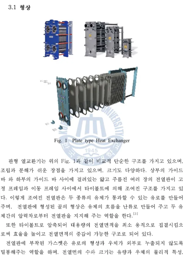
Fig. 1 Plate type Heat Exchanger
Fig. 1 , , . . , .[3] . , ,
.
.
Fig.2 .
, .
No Description Material Q’ty Remarks
1 Fixed Frame A516-70 1 120t
2 Remove Frame A516-70 1 80t
3 Plate / Gasket A240-316L/
EPDM 595 0.6t
4 Upper G / B A36 1 H 250 x125
5 Lower G / B A312TP316L 1 80 x 80
6 Tight Bolt A193-B7 6/8
8 Support A36 1 250 x 90
9,10 Base plate A36 / A283-C 6 / 1
200x150 x 25t / 25t
19 Setting Bolt A307-C 14 M50
20 Connecting Bolt A193-B7
3.2
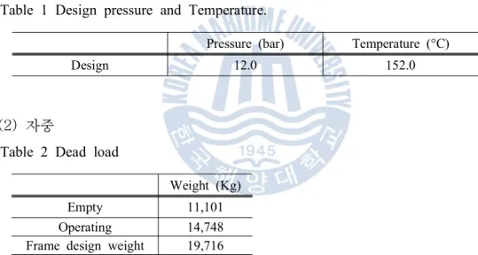
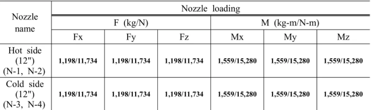
. , . . Table 1 12.0 bar 152°C , Table 2 11,101 kg , 14,748 kg . ( ), 19,716 kg . , . . , 50% , , 1.5 . Table 3 , API 662( ) . . Fz , Fx Fy . Mz , Mx My . Table 4 1.3 15.6bar . 1 , . ASCE7-05( ) .ASCE7-05(Table 6-2, Table 6-3, Table 6-4, Figure
6-21) .
.
IBC 2006 Building Mounted, (ASCE7-05 Table 13.6-1) . (6) . . . . . (1)
Table 1 Design pressure and Temperature.
Pressure (bar) Temperature (°C)
Design 12.0 152.0
(2)
Table 2 Dead load
Weight (Kg)
Empty 11,101
Operating 14,748
Frame design weight 19,716
( Plate w/Gasket : 10.57kg/sheet, fluid weight :14,748 -11,101 = 3,647 kg ) ( Frame design weight : 14,748 + (10.57+3,647/595)*595*0.5 = 19,716 kg )
(3)
Table 3 Nozzle loads Nozzle name Nozzle loading F (kg/N) M (kg-m/N-m) Fx Fy Fz Mx My Mz Hot side (12") (N-1, N-2) 1,198/11,734 1,198/11,734 1,198/11,734 1,559/15,280 1,559/15,280 1,559/15,280 Cold side (12") (N-3, N-4) 1,198/11,734 1,198/11,734 1,198/11,734 1,559/15,280 1,559/15,280 1,559/15,280 (4)
Table 4 Hydrostatic test pressure Hydrostatic Pressure (bar)
15.6
(5)
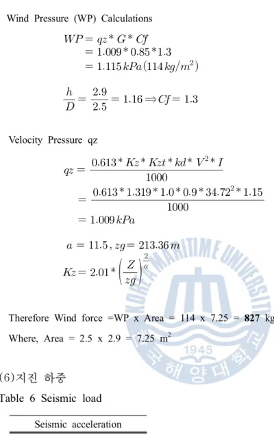
Table 5 Wind load Wind load (kg)
827
Basic wind speed V : 125 km/h (34.72 m/s) Exposure : D
Importance factor I : 1.15
Height above ground level Z = 16m + 2.9m = 18.9 m Wind Directionality Factor Kd = 0.9
Wind Pressure (WP) Calculations ⇒ Velocity Pressure qz
Therefore Wind force =WP x Area = 114 x 7.25 = 827 kg Where, Area = 2.5 x 2.9 = 7.25 m2
(6)
Table 6 Seismic load Seismic acceleration 0.57g (horizontal direction) Response Factor : 3.0 Fa = 1.0, Fv = 1.3 Importance factor I = 1.25 Site Class : C, Ss = 1.425 ap = 1 , Rp = 2.5
= (8,406/ 14,748) = 0.57g 0.7 .3.3
Table 7 , ,
.
ASME Section II Boiler and pressure vessel code Part D[12] . , , . AISI 0.66*Sy , 0.6*Sy . Table. 7 , .
. ASME Section VIII
div.1,div.2[8],[9] .
3 . (center of fixed
frame), (edge of fixed frame), (near the
nozzle) . .
1 (general membrane stress) 1 (primary
bending stress) ,
1 (local membrane stress) 2 (secondary stress) .
.
Table 8 .
Table 7 Material summary
Material Allowable Stress (Sa) (MPa) Yield Strength (Sy) (MPa) Modulus of Elasticity (E) (MPa)
Fixed Frame A516-70 138 232 194880
Remove Frame A516-70 138 232 194880
Plate A240-316L 87.2 131 185880
-Table 8 Allowable limit for Fixed frame
Lower G/B A312TP304 115 154 185880
Support A36 144.5 219 194880
Base Plate A36 / A283-C 109.8 219 / 183 194880
Setting bolt A307-C - -
-Connecting bolt A193-B7 - -
-Center of Fixed frame
Loading Stress Limit
Pm Pm + Pb
Internal pressure 1.0 S 1.5S
Pm : General Membrane stress, Pb : Primary Bending stress Edge of Fixed frame
Loading Stress Limit
PL PL + Q
Internal pressure 1.5 S 3S
PL: Local Membrane stress, Q : Secondary Bending stress
Near the nozzle
Loading Stress Limit
PL PL + Q
Internal pressure + Nozzle load 1.5 S 3S
PL: Local Membrane stress, Q : Secondary Bending stress
Hydrostatic test condition
Loading Stress Limit
Pm Pm + Pb
Hydrostatic pressure 0.95Sy 1.43 Sy for Pm < 0.67Sy Pm : General Membrane stress, Pb : Primary Bending stress
4
4.1
.
, .
4.1.1
(start plate) O-ring .
blank plate(end plate)
. Plate pack (tightening bolt)
.[1]
.
Table 9 Frame design input data
Design Pressure 12 bar
Design Temperature 152°C
Ambient Temperature 85°C
FRAME
Material A516-70N
Allowable Stress at Design T. (Sfo) 14.08
Allowable Stress at Ambient T.(Sfa) 14.08
Ref. ASME SECTION II PART D
BOLT
Material A193-B7
Allowable Stress at Design T.(So) 17.54
Allowable Stress at Ambient T.(Sa) 17.54
Effective Diameter (db) 36.40 mm MIN. Number & Size 14 [M39]
Gasket
Material EPDM
Design Seating Stress (y) 0.14
Factor (m) 1.00
Long span of frame measured perpendicular to short span : D-2358 mm Short span : d-870mm
Perimeter measured along the centers of the bolts holes L-6158.17 mm Distance across bolt holes B-974 mm
Attachment Factor
(Ref. ASME SEC.VIII, Div.1 FIG.UG-34) C-0.3
1. Calculation of total bolt load
Equation Calculated value
×× 246175.20 kgf × × × ×× 9296.64 kgf 255471.84 kgf × × × 2294.71 kgf 14561.78 mm2 ×× 14562.91 mm2
Total required bolt areas, < Total Actual bolt areas,
So, Bolt size is adequate.
×2. Calculation of Frame thickness
120mm 76mm
.
Equation Calculated value
Z Factor ( )
×
2.5Gasket moment arm
52.0 mm
Minimum Thickness of frame
Operating condition Gasket seating condition
× × × × × × × × 75.88 mm
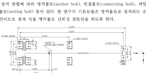
× × × × × 30.32 mm4.1.2
(anchor bolt), (connecting bolt),
(setting bolt) .
.
Table 10 Anchor bolt design input data
(1) Geometry and properties
(2) Max. tensile stress of anchor bolt (ft)
Bolt size 2.00 inch
Number of bolt(N) 14 EA
Number of threads per inch(n) 4.5
Bolt Material A307-C
Nominal Tensile stress for bolt (Fnt) 3,166 (45 ksi)
Nominal Shear Strength for bolt (Fnv) 1,689 (24 ksi)
Equation Calculated value
× = 2.498 inch2 ( = 2.00 inch ) ( = 4.5 ) 16.12 cm2 × × × × 1531 mm × × × × × × × × 6718791 cm 4 × × × × × × × × 315546 cm 4 7034337 cm4
(3) Max. shear stress of anchor bolt (ft) (4) Allowable stress Equation Calculated value × × × × 412 kg/cm2 Equation Calculated value
×
×
162 kg/cm2Equation Calculated value
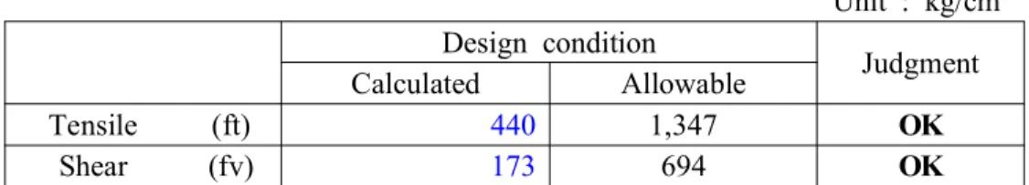
Tensile stress (ft) 1,347 kg/cm2 1,583 kg/cm2 1,347 kg/cm2 × × ≤ 3,166 kg/cm2 Shear stress (fv) 694 kg/cm2 844 kg/cm2 694 kg/cm2
Table 11 Tension and shear stress check . Unit : kg/cm2 Design condition Judgment Calculated Allowable Tensile (ft) 440 1,347 OK Shear (fv) 173 694 OK
4.2
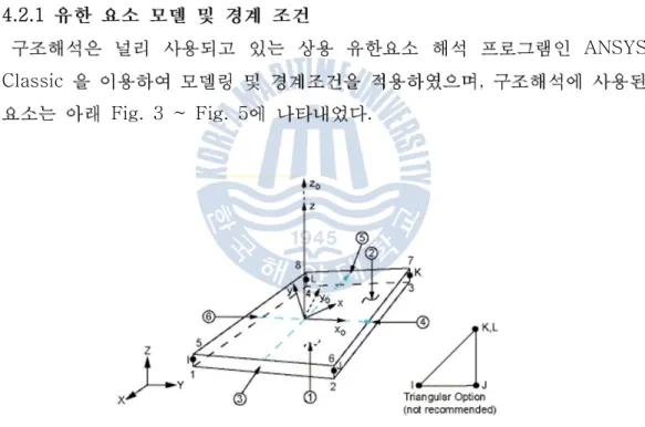
(node) , (element) . , , , , . .[13] 4.2.1 ANSYS Classic , Fig. 3 ~ Fig. 5 .Fig. 3 Structural shell 181 element in ANSYS
Fig. 3
(4node) .
Fig. 4 Structural beam 188 element in ANSYS
Fig. 4 , ,
(3-D, 2node) . .
, .
Fig. 5 Structural solid 185 in ANSYS
Fig. 5 , ,
(3-D, 8node) . , .
. , .
ANSYS APDL(ANSYS
Parametric Design Language) .
Fig. 6 .
Fig. 6 Finite element model for full - FEM analysis
, ,
Fig. 7 Applied boundary conditions for full model
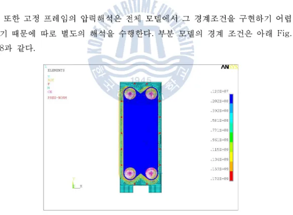
. Fig.
8 .
4.2.2
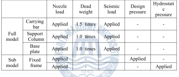
. , . . Table 12 .Table 12 Analysis case
. 3.2 1.5 , . 1.3 . . . Nozzle
load weightDead Seismicload pressureDesign
Hydrostati c pressure Full model Carrying
bar Applied 1.5 times Applied -
-Support
Column Applied 1.0 times Applied -
-Base
plate Applied 1.0 times Applied -
-Sub model Fixed frame Applied - Applied -Applied - - Applied
4.2.3
,
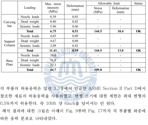
Table. 13 .
Table 13 Analysis Results for each components
3.3 ASME Section II Part D
,
0.5% . 100ft 6inch .
Fig. 9 Fig. 17
.
Loading Max. stressintensity (MPa)
Deformation (mm)
Allowable limit Status Stress (MPa) Deformation(mm) Carrying bar Nozzle loads 0.39 0.03 - -Dead weight 0.40 0.02 Seismic loads 5.96 0.46 - -Total 6.75 0.51 144.5 10.4 OK Support Column Nozzle loads 4.65 0.09 - -Dead weight 4.67 0.08 Seismic loads 2.09 0.42 - -Total 11.41 0.59 144.5 13.0 OK Base Plate Nozzle loads 10.6 - - -Dead weight 11.8 - -Seismic loads 22.3 - - -Total 44.7 - 109.8 - OK
Fig. 9 Distribution of stress intensity due to nozzle loads for carrying bar
Fig. 11 Distribution of stress intensity due to seismic loads for carrying bar
Fig. 13 Distribution of stress intensity due to dead weight for support column
Fig. 15 Distribution of stress intensity due to nozzle loads for base plate
Fig. 17 Distribution of stress intensity due to seismic loads for base plate Fig. 18
Fig. 21 .
1.3 ,
Table 14 .
Table 14 Analysis results for fixed frame
Location
Stress Intensity (MPa)
Remark Category Pm Status Pm + Pb Status
Design HYD Design HYD
Center of Fixed frame Actual 9.13 11.4 OK 33.0 41.7 OK Path 1 of Fig.17 APPENDIX A Allowable 138 220.4 207 332
Location Stress Intensity (MPa) Remark
Category PL Status PL + Q Status
Edge of Fixed frame Actual 12.1 OK 26.8 OK Path 2 of Fig. 17 APPENDIX A Allowable 207 414
Fig. 18 ,
ANSYS Output APPENDIX .
Fig. 19 .
Fig. 18 Path location on fixed frame
Location Stress Intensity (MPa) Remark
Category PL Status PL + Pb Status
Near the nozzles Actual 17.2 OK 53.4 OK Path 3 of Fig. 17 APPENDIX A Allowable 207 414
(a) Front view
(b) Back view
5
. , . , . . . FE Fig. 20 .5.1
. (local mode) , . . .[2]~[3] , (mode coefficient) . 0.001 0.1% . . ANSYS 12.0 , Block Lanczos . 100 , Table 15 , 1 2 Fig. 21 Fig. 22 .Table 15 Modal Frequencies and effective masses
mode Frequency(Hz) effective mass(X) effective mass(Y) effective mass(Z) 1 7.566 0.986674 1.46E-05 4.75E-05 2 9.253 1.02E-05 9.74662 30.6957 3 20.97 4.13E-03 2.41E-08 5.16E-08 4 40.04 9.90E-02 2.35E-07 3.79E-07 5 46.35 3.89E-02 1.30E-06 1.32E-06 6 61.23 41.5557 6.69E-07 2.27E-05 7 62.71 7.90E-02 1.05E-06 6.46E-07 8 64.2 3.04E-03 1.17E-07 4.84E-08 9 70.26 0.176542 2.39E-04 8.47E-05 10 88 8.21E-03 9.98E-05 1.29E-07 11 88.38 8.62E-08 0.123953 1.50E-03 12 99.63 3.63566 1.01E-07 4.26E-05 13 103.5 1.25939 4.08E-03 3.45E-04 14 107.4 0.183442 9.40E-03 1.24E-03 15 113.4 3.74E-03 0.417037 8.37E-02 16 131.7 2.51E-05 4.63E-07 1.11E-05 17 147.2 1.61E-04 7.76E-07 2.27E-06 18 161 2.62E-06 1.01093 0.755312 19 161.4 7.29E-04 1.04E-03 7.93E-04 20 179.2 4.50E-06 6.83E-05 6.66E-05 21 189.4 1.43E-04 8.34E-07 1.06E-06 22 203.4 6.10E-06 7.46317 18.5936 23 221.7 6.00E-05 5.98E-03 6.40E-03 24 222.7 1.09E-07 8.57531 8.27572 25 231.7 3.19E-04 1.07E-06 3.23E-07 26 252.8 1.22E-03 3.09E-05 1.46E-06 27 258.3 1.74E-02 6.46E-05 3.13E-06 28 266 1.64E-03 5.31E-06 6.73E-07 29 271 1.98E-02 2.95E-12 3.44E-06 30 274.5 9.19E-04 2.88E-06 7.32E-07 31 286.7 2.73E-05 0.786123 3.32E-03 32 310 3.68E-03 2.94E-04 1.09E-05 33 314.7 0.119751 9.07E-03 2.05E-04 34 315.4 10.241 3.76E-02 4.11E-04 35 318.9 1.68E-02 26.6336 0.381229 36 322.1 2.86E-03 8.96E-02 1.02E-03 37 347.6 4.82E-05 1.13862 3.63E-03 38 353.8 4.85E-03 2.65E-03 6.80E-06 39 361.2 1.88E-04 9.83E-05 1.65E-07 40 369.8 3.41E-03 2.97E-05 8.70E-08 41 382.9 3.34E-05 0.972132 1.27E-02 42 404.2 7.70E-06 9.27E-07 2.50E-09 43 404.9 1.14E-04 2.44E-06 6.43E-10
44 448.5 9.45E-05 3.84E-07 3.23E-10 45 449.2 8.93E-06 6.65E-07 5.06E-09 46 481.9 2.96E-11 0.396975 1.56E-04 47 492.8 1.65E-04 4.87E-12 3.15E-11 48 494.9 2.42E-05 9.05E-06 1.09E-07 49 513 2.11E-03 1.53E-06 5.90E-08 50 515.9 6.99E-06 1.47E-02 2.66E-04 51 538 3.97E-10 4.39E-05 3.43E-07 52 540.4 3.23E-08 7.17E-05 3.48E-05 53 561.8 1.90E-10 4.54E-03 3.89E-04 54 575 1.69E-05 1.28E-05 4.88E-03 55 582.8 1.69E-09 3.26E-04 1.08E-06 56 584.7 2.78E-12 5.13E-04 1.61E-07 57 607.9 4.68E-10 1.46E-03 1.86E-05 58 627.3 1.67E-09 1.37E-03 7.94E-06 59 635 2.91E-09 2.98E-03 1.13E-05 60 652.3 1.99E-08 3.80E-03 4.48E-05 61 677.2 2.83E-09 3.05E-04 4.56E-06 62 688.3 8.11E-10 5.52E-09 1.05E-06 63 709.6 3.92E-05 2.12E-06 4.34E-02 64 723.9 1.55E-09 6.81E-05 1.35E-06 65 736.3 3.02E-09 2.45E-07 1.67E-06 66 767.1 2.10E-05 1.07E-07 2.97E-03 67 770.2 1.01E-09 9.57E-06 1.32E-07 68 771.8 7.87E-11 2.90E-05 8.75E-08 69 789.7 2.94E-10 1.65E-06 2.37E-07 70 797.3 3.68E-12 4.93E-04 4.29E-08 71 820.3 1.96E-13 4.73E-05 2.70E-09 72 837.4 2.45E-10 9.15E-06 9.18E-08 73 869.6 5.65E-10 7.25E-04 4.55E-09 74 872.4 2.77E-07 0.163678 2.73E-06 75 886 5.00E-09 2.69E-03 6.52E-07 76 910.1 3.46E-09 6.70E-05 4.99E-07 77 920.1 6.42E-11 1.76E-05 2.18E-09 78 925.4 7.11E-06 6.85E-07 1.61E-03 79 930.6 2.11E-05 1.83E-05 2.22E-03 80 933.1 1.28E-06 1.54E-04 5.54E-05 81 952.8 6.66E-08 2.54E-04 8.02E-07 82 970.5 1.40E-09 1.78E-04 5.32E-08 83 993.4 5.70E-09 8.72E-04 2.38E-07 84 1015 5.82E-05 9.01E-05 2.48E-03 85 1020 1.14E-06 1.96E-03 4.76E-05 86 1035 1.51E-07 6.68E-03 5.78E-06 87 1049 1.19E-10 2.87E-06 2.28E-08
89 1104 1.34E-10 5.16E-05 6.92E-09 90 1130 7.87E-11 7.02E-05 1.99E-11 91 1147 6.35E-05 3.69E-09 1.90E-03 92 1157 1.62E-10 3.23E-05 2.92E-08 93 1184 1.26E-10 4.01E-05 1.87E-09 94 1209 4.02E-08 1.23E-05 8.79E-07 95 1222 1.23E-02 5.93E-05 0.256213 96 1235 6.96E-06 5.84E-03 1.11E-04 97 1240 1.77E-06 3.54E-03 2.60E-05 98 1244 1.59E-05 4.03E-02 2.16E-04 99 1277 9.18E-10 1.15E-04 9.86E-08 100 1296 3.71E-10 2.35E-05 5.37E-09
Fig. 21 First mode shape
5.1.1
Table 16 2.3
.
90% .
Table 16 Sum of effective masses
, 97% . Fig. 23 . , X 6 , Y 35 , Z 2 . X( - ) 99% , Y( - ) ( - ) 98%, 97% X . Actual weight Sum of effective mass (lb) Ration to total mass (%) X-direction 22,926 22,708 99.0 Y-direction 22,664 98.8 Z-direction 22,294 97.2
5.2
. (response spectrum) . Biot Housner . . [14] 5.2.1 . . . . . . . .acceleration A) . . (22) (23) (24) . (22) (23) (24) , , , D, V A V A D . ≡ (25) ≡ (26) ≡
(27) () (28) V . (28)(29) () () m A . (29)
(base shear coefficient) (lateral force
coefficient) . (30) . (30) (22) . (23) (24) . . . Fig. 24 Fig. 26
. OBE(operating basis earthquake) 2%
SSE(safe shutdown earthquake ) 50% , SSE
3% .
,
5.2.2
5 . 4 , . (OBE, SSE) . , . ANSYS. SRSS(Square Root of the Sum
of the Squares) (31) DSUM(Double Sum Method) (32) .
(31)
(32) , . . . .Fig. 27 Reaction test for spectrum analysis (1-point support) Fig. 27 , 10kg . , All DOF . ( : 9.8, (9.8 * 4 =39.2) . 39.2 * (10kg) = 392 N , .
Fig. 28 Reaction test for spectrum analysis results (1-point support, Input Acceleration. - Y-dir)
.
.
Fig. 29 Reaction test for spectrum analysis results (1-point support. Input Acceleration. - X-dir)
Fig. 29
. Fig. 30 ( )
Fig. 30 Reaction test for spectrum analysis (4-point support) 1point . , . , , 5.2.10 5.2.11 . Fig. 31 4-point .
Fig. 31 Reaction test for spectrum analysis results (4-point support. Input Acceleration. - Y-dir)
Fig. 31 , Fx
, , (Fz)
. .
.
Fig. 32 Reaction test for spectrum analysis (Suggest model)
Fig. 33
, , .
Fig. 33 Reaction test for spectrum analysis results (Suggest model. Input Acceleration. - X-dir)
6
. .6.1
. 3 , , . Visual BasicForm [15]~[17] ANSYS APDL .
6.1.2 ANSYS APDL . , , . APDL . , , , , . Fig. 34 APDL .
6.2
Fig. 35 Visual Basic .
(A)
(B) . input data
(C) ,
.
, (D) .
ANSYS FEM (E)
.
6.2.1
Page Fig. 36 Fig. 41 .
Fig. 36 Front page in visual basic module
Fig. 38 Beam section page in visual basic module
Fig. 40 Base plate page in visual basic module
7
, . FEM . 1. (1) 1.5 . (2) . . 2.(1) , ASME Section II Part
D , .
(2)
0.66Sy , Base plate
0.6Sy . (3) , AISI 100ft 6inch . 3. (1) , , . (2)
, FEM .
[1] , “ ” ,
33 6 2009.9 801p~811p
[2] Weiya jin, "Comparison of two FEA models for calculating stresses in shell-and tube heat exchanger" , International Journal of Pressure Vessels and Piping 81 (2004) pp.563-567
[3] , “
”, 10 3 2006.06.pp.21~33P
[4] , “ ” , 35 9 , 1995 , 794p~804p
[5] IBC2006, ICC, International Building Code, International Code Council, January 2006.
[6] ASCE7-05, SEI, Structural Engineering Institute of the American Society of Civil Engineers.
[7] API 662, Latest Edition, American Petroleum Institute. [8] ASME CODE Section VIII Div1, 2010 Edition. [9] ASME CODE Section VIII Div2, 2010 Edition. [10] AISI, American iron and steel institute.
[11] , “ ” ,
[12] ASME CODE Section II, Part D, 2010 Edition.
[13] ( ) “ ”, 5 .
[14] , “ ”,
2008, .
[15] , , www.vbbank.net .
[16] Visual basic for windows, , , .
APPENDIX A : Design Pressure
Linearlized Stress Intensity for Path 1 of fixed frame each load cases
PRINT LINEARIZED STRESS THROUGH A SECTION DEFINED BY PATH= 1 DSYS= 0
***** POST1 LINEARIZED STRESS LISTING ***** INSIDE NODE =1000301 OUTSIDE NODE =1002699
LOAD STEP 1 SUBSTEP= 1 TIME= 1.0000 LOAD CASE= 0
THE FOLLOWING X,Y,Z STRESSES ARE IN THE GLOBAL COORDINATE SYSTEM.
** MEMBRANE **
SX SY SZ SXY SYZ SXZ 0.8475E+07 0.2305E+07 -0.6010E+06 3106. 2488. -0.5147E+06
S1 S2 S3 SINT SEQV 0.8504E+07 0.2305E+07 -0.6301E+06 0.9134E+07 0.8077E+07
** BENDING ** I=INSIDE C=CENTER O=OUTSIDE
SX SY SZ SXY SYZ SXZ I 0.2346E+08 0.8169E+07 -0.4567E+06 -8265. 257.2 -319.8 C 0.000 0.000 0.000 0.000 0.000 0.000 O -0.2346E+08 -0.8169E+07 0.4567E+06 8265. -257.2 319.8
S1 S2 S3 SINT SEQV I 0.2346E+08 0.8169E+07 -0.4567E+06 0.2392E+08 0.2098E+08 C 0.000 0.000 0.000 0.000 0.000 O 0.4567E+06 -0.8169E+07 -0.2346E+08 0.2392E+08 0.2098E+08
** MEMBRANE PLUS BENDING ** I=INSIDE C=CENTER O=OUTSIDE SX SY SZ SXY SYZ SXZ
I 0.3194E+08 0.1047E+08 -0.1058E+07 -5159. 2746. -0.5150E+06 C 0.8475E+07 0.2305E+07 -0.6010E+06 3106. 2488. -0.5147E+06 O -0.1499E+08 -0.5864E+07 -0.1442E+06 0.1137E+05 2231. -0.5144E+06
S1 S2 S3 SINT SEQV I 0.3195E+08 0.1047E+08 -0.1066E+07 0.3301E+08 0.2902E+08 C 0.8504E+07 0.2305E+07 -0.6301E+06 0.9134E+07 0.8077E+07 O -0.1264E+06 -0.5864E+07 -0.1501E+08 0.1488E+08 0.1300E+08
** PEAK ** I=INSIDE C=CENTER O=OUTSIDE
SX SY SZ SXY SYZ SXZ I -0.1280E+07 -0.1424E+07 -0.7314E+06 1932. 2363. 0.2505E+06 C -1447. 1470. 1.734 -63.00 -2049. -0.2224E+06 O 0.1285E+07 0.1419E+07 0.7314E+06 -1720. 2092. 0.2509E+06
S1 S2 S3 SINT SEQV I -0.6342E+06 -0.1377E+07 -0.1424E+07 0.7899E+06 0.7675E+06 C 0.2217E+06 1471. -0.2232E+06 0.4449E+06 0.3853E+06 O 0.1419E+07 0.1381E+07 0.6346E+06 0.7847E+06 0.7665E+06
** TOTAL ** I=INSIDE C=CENTER O=OUTSIDE
SX SY SZ SXY SYZ SXZ I 0.3066E+08 0.9049E+07 -0.1789E+07 -3226. 5109. -0.2646E+06 C 0.8474E+07 0.2306E+07 -0.6010E+06 3043. 439.3 -0.7371E+06 O -0.1370E+08 -0.4445E+07 0.5871E+06 9652. 4323. -0.2635E+06 S1 S2 S3 SINT SEQV TEMP I 0.3066E+08 0.9049E+07 -0.1791E+07 0.3245E+08 0.2862E+08 0.000 C 0.8533E+07 0.2306E+07 -0.6604E+06 0.9194E+07 0.8127E+07 O 0.5920E+06 -0.4445E+07 -0.1371E+08 0.1430E+08 0.1256E+08 0.000
APPENDIX A : Test Pressure
Linearlized Stress Intensity for Path 1 of fixed frame each load cases
PRINT LINEARIZED STRESS THROUGH A SECTION DEFINED BY PATH= 1 DSYS= 0
***** POST1 LINEARIZED STRESS LISTING ***** INSIDE NODE =1000301 OUTSIDE NODE =1002699
LOAD STEP 1 SUBSTEP= 1 TIME= 1.0000 LOAD CASE= 0
THE FOLLOWING X,Y,Z STRESSES ARE IN THE GLOBAL COORDINATE SYSTEM.
** MEMBRANE **
SX SY SZ SXY SYZ SXZ 0.1049E+08 0.2663E+07 -0.7811E+06 5243. 2320. -0.6758E+06
S1 S2 S3 SINT SEQV 0.1053E+08 0.2663E+07 -0.8215E+06 0.1135E+08 0.1007E+08
** BENDING ** I=INSIDE C=CENTER O=OUTSIDE
SX SY SZ SXY SYZ SXZ I 0.2983E+08 0.1047E+08 -0.5663E+06 -8954. 275.3 -455.2 C 0.000 0.000 0.000 0.000 0.000 0.000 O -0.2983E+08 -0.1047E+08 0.5663E+06 8954. -275.3 455.2
S1 S2 S3 SINT SEQV I 0.2983E+08 0.1047E+08 -0.5663E+06 0.3039E+08 0.2665E+08 C 0.000 0.000 0.000 0.000 0.000 O 0.5663E+06 -0.1047E+08 -0.2983E+08 0.3039E+08 0.2665E+08
** MEMBRANE PLUS BENDING ** I=INSIDE C=CENTER O=OUTSIDE SX SY SZ SXY SYZ SXZ
I 0.4031E+08 0.1313E+08 -0.1347E+07 -3712. 2596. -0.6762E+06 C 0.1049E+08 0.2663E+07 -0.7811E+06 5243. 2320. -0.6758E+06 O -0.1934E+08 -0.7802E+07 -0.2148E+06 0.1420E+05 2045. -0.6753E+06
S1 S2 S3 SINT SEQV I 0.4032E+08 0.1313E+08 -0.1358E+07 0.4168E+08 0.3665E+08 C 0.1053E+08 0.2663E+07 -0.8215E+06 0.1135E+08 0.1007E+08 O -0.1910E+06 -0.7802E+07 -0.1936E+08 0.1917E+08 0.1672E+08
** PEAK ** I=INSIDE C=CENTER O=OUTSIDE
SX SY SZ SXY SYZ SXZ I -0.1628E+07 -0.1815E+07 -0.9344E+06 2456. 3426. 0.3290E+06 C -1954. 1994. -1.234 -73.33 -3005. -0.2921E+06 O 0.1634E+07 0.1808E+07 0.9344E+06 -2207. 3140. 0.3296E+06
S1 S2 S3 SINT SEQV I -0.8031E+06 -0.1759E+07 -0.1815E+07 0.1012E+07 0.9851E+06 C 0.2912E+06 1995. -0.2931E+06 0.5843E+06 0.5060E+06 O 0.1808E+07 0.1765E+07 0.8036E+06 0.1005E+07 0.9838E+06
** TOTAL ** I=INSIDE C=CENTER O=OUTSIDE
SX SY SZ SXY SYZ SXZ I 0.3869E+08 0.1131E+08 -0.2282E+07 -1256. 6021. -0.3472E+06 C 0.1049E+08 0.2665E+07 -0.7811E+06 5169. -684.9 -0.9679E+06 O -0.1770E+08 -0.5994E+07 0.7196E+06 0.1199E+05 5185. -0.3458E+06
S1 S2 S3 SINT SEQV TEMP I 0.3869E+08 0.1131E+08 -0.2285E+07 0.4097E+08 0.3615E+08 0.000 C 0.1057E+08 0.2665E+07 -0.8637E+06 0.1143E+08 0.1014E+08 O 0.7261E+06 -0.5994E+07 -0.1771E+08 0.1844E+08 0.1616E+08 0.000
APPENDIX A : Design Pressure
Linearlized Stress Intensity for Path 2 of fixed frame each load cases
PRINT LINEARIZED STRESS THROUGH A SECTION DEFINED BY PATH= 2 DSYS= 0
***** POST1 LINEARIZED STRESS LISTING ***** INSIDE NODE =1004623 OUTSIDE NODE =1006741
LOAD STEP 1 SUBSTEP= 1 TIME= 1.0000 LOAD CASE= 0
THE FOLLOWING X,Y,Z STRESSES ARE IN THE GLOBAL COORDINATE SYSTEM.
** MEMBRANE **
SX SY SZ SXY SYZ SXZ 0.2399E+07 0.3156E+07 0.8089E+07 0.5092E+06 -0.2164E+07 0.4815E+07
S1 S2 S3 SINT SEQV 0.1118E+08 0.3410E+07 -0.9413E+06 0.1212E+08 0.1063E+08
** BENDING ** I=INSIDE C=CENTER O=OUTSIDE
SX SY SZ SXY SYZ SXZ I 0.5176E+07 0.6605E+07 0.1258E+08 -0.8074E+06 -0.3742E+07 0.5444E+07 C 0.000 0.000 0.000 0.000 0.000 0.000 O -0.5176E+07 -0.6605E+07 -0.1258E+08 0.8074E+06 0.3742E+07 -0.5444E+07
S1 S2 S3 SINT SEQV I 0.1680E+08 0.5562E+07 0.1994E+07 0.1481E+08 0.1338E+08 C 0.000 0.000 0.000 0.000 0.000 O -0.1994E+07 -0.5562E+07 -0.1680E+08 0.1481E+08 0.1338E+08
** MEMBRANE PLUS BENDING ** I=INSIDE C=CENTER O=OUTSIDE SX SY SZ SXY SYZ SXZ
I 0.7575E+07 0.9761E+07 0.2067E+08 -0.2982E+06 -0.5907E+07 0.1026E+08 C 0.2399E+07 0.3156E+07 0.8089E+07 0.5092E+06 -0.2164E+07 0.4815E+07 O -0.2776E+07 -0.3449E+07 -0.4487E+07 0.1317E+07 0.1578E+07 -0.6289E+06
S1 S2 S3 SINT SEQV I 0.2788E+08 0.9053E+07 0.1072E+07 0.2680E+08 0.2384E+08 C 0.1118E+08 0.3410E+07 -0.9413E+06 0.1212E+08 0.1063E+08 O -0.1638E+07 -0.2938E+07 -0.6137E+07 0.4499E+07 0.4011E+07
** PEAK ** I=INSIDE C=CENTER O=OUTSIDE
SX SY SZ SXY SYZ SXZ I 0.2522E+07 0.2811E+07 0.8697E+06 -0.7839E+07 -0.3457E+07 0.4010E+07 C -0.1258E+07 -0.1951E+07 -0.4690E+07 0.1440E+07 0.1980E+07 -0.1962E+07 O 0.1958E+07 0.3262E+07 0.4375E+07 -0.4274E+07 -0.2172E+07 0.2275E+07
S1 S2 S3 SINT SEQV I 0.1284E+08 -0.1414E+07 -0.5219E+07 0.1805E+08 0.1648E+08 C -0.7512E+05 -0.1042E+07 -0.6781E+07 0.6706E+07 0.6279E+07 O 0.9038E+07 0.2290E+07 -0.1733E+07 0.1077E+08 0.9427E+07
** TOTAL ** I=INSIDE C=CENTER O=OUTSIDE
SX SY SZ SXY SYZ SXZ I 0.1010E+08 0.1257E+08 0.2153E+08 -0.8137E+07 -0.9364E+07 0.1427E+08 C 0.1142E+07 0.1205E+07 0.3399E+07 0.1949E+07 -0.1838E+06 0.2853E+07 O -0.8180E+06 -0.1876E+06 -0.1115E+06 -0.2957E+07 -0.5939E+06 0.1646E+07
S1 S2 S3 SINT SEQV TEMP I 0.3733E+08 0.6727E+07 0.1476E+06 0.3718E+08 0.3437E+08 0.000 C 0.5567E+07 0.1993E+07 -0.1814E+07 0.7381E+07 0.6393E+07 O 0.3210E+07 -0.6361E+06 -0.3691E+07 0.6901E+07 0.5990E+07 0.000
APPENDIX A : Design Pressure
Linearlized Stress Intensity for Path 3 of fixed frame each load cases
PRINT LINEARIZED STRESS THROUGH A SECTION DEFINED BY PATH= 3 DSYS= 0
***** POST1 LINEARIZED STRESS LISTING ***** INSIDE NODE =1011413 OUTSIDE NODE =1007466
LOAD STEP 1 SUBSTEP= 1 TIME= 1.0000 LOAD CASE= 0
THE FOLLOWING X,Y,Z STRESSES ARE IN THE GLOBAL COORDINATE SYSTEM.
** MEMBRANE **
SX SY SZ SXY SYZ SXZ 0.9961E+07 0.4187E+07 0.9861E+07 0.7527E+07 -0.3142E+07 0.9212E+06
S1 S2 S3 SINT SEQV 0.1535E+08 0.1048E+08 -0.1820E+07 0.1717E+08 0.1533E+08
** BENDING ** I=INSIDE C=CENTER O=OUTSIDE
SX SY SZ SXY SYZ SXZ I -0.1888E+08 -0.7795E+07 -0.1477E+08 -0.1622E+08 0.5940E+07 -0.1513E+07 C 0.000 0.000 0.000 0.000 0.000 0.000 O 0.1888E+08 0.7795E+07 0.1477E+08 0.1622E+08 -0.5940E+07 0.1513E+07
S1 S2 S3 SINT SEQV I 0.5425E+07 -0.1607E+08 -0.3080E+08 0.3623E+08 0.3156E+08 C 0.000 0.000 0.000 0.000 0.000 O 0.3080E+08 0.1607E+08 -0.5425E+07 0.3623E+08 0.3156E+08
** MEMBRANE PLUS BENDING ** I=INSIDE C=CENTER O=OUTSIDE SX SY SZ SXY SYZ SXZ
I -0.8923E+07 -0.3608E+07 -0.4906E+07 -0.8689E+07 0.2798E+07 -0.5916E+06 C 0.9961E+07 0.4187E+07 0.9861E+07 0.7527E+07 -0.3142E+07 0.9212E+06 O 0.2884E+08 0.1198E+08 0.2463E+08 0.2374E+08 -0.9082E+07 0.2434E+07
S1 S2 S3 SINT SEQV I 0.3621E+07 -0.5568E+07 -0.1549E+08 0.1911E+08 0.1655E+08 C 0.1535E+08 0.1048E+08 -0.1820E+07 0.1717E+08 0.1533E+08 O 0.4614E+08 0.2656E+08 -0.7239E+07 0.5338E+08 0.4677E+08
** PEAK ** I=INSIDE C=CENTER O=OUTSIDE
SX SY SZ SXY SYZ SXZ I 9255. 0.1030E+07 0.6341E+07 0.2124E+07 -0.3568E+07 0.9596E+06 C 0.5204E+06 0.1002E+06 -0.3815E+07 -0.4382E+06 0.2046E+07 -0.7498E+05 O -0.5372E+07 0.8568E+06 0.3524E+07 0.5595E+07 -0.1261E+08 0.6969E+07
S1 S2 S3 SINT SEQV I 0.8134E+07 0.1983E+07 -0.2737E+07 0.1087E+08 0.9442E+07 C 0.1236E+07 0.2605E+06 -0.4691E+07 0.5927E+07 0.5505E+07 O 0.1499E+08 0.1158E+07 -0.1714E+08 0.3213E+08 0.2791E+08
** TOTAL ** I=INSIDE C=CENTER O=OUTSIDE
SX SY SZ SXY SYZ SXZ I -0.8913E+07 -0.2578E+07 0.1434E+07 -0.6565E+07 -0.7704E+06 0.3680E+06 C 0.1048E+08 0.4288E+07 0.6046E+07 0.7088E+07 -0.1096E+07 0.8462E+06 O 0.2347E+08 0.1284E+08 0.2815E+08 0.2934E+08 -0.2169E+08 0.9403E+07 S1 S2 S3 SINT SEQV TEMP I 0.2339E+07 0.6394E+06 -0.1304E+08 0.1537E+08 0.1460E+08 0.000 C 0.1512E+08 0.6330E+07 -0.6363E+06 0.1576E+08 0.1368E+08 O 0.5102E+08 0.3548E+08 -0.2204E+08 0.7305E+08 0.6666E+08 0.000