1. INTRODUCTION
In industry, the machining tools with three orthogonal actuators are used to do the machining work. However, these are able to apply to plain work, not to complex 3D work because of lack of d.o.f.. Many researchers make a lot of effort to the application of high d.o.f robot in machining work such as cutting, milling, grilling, etc. However, this kind of work requires robot to have high stiffness, which cannot be provided by conventional serial robot owing to the cantilever structure. Since Stewart-Gough[1] introduced a parallel actuated manipulator, the parallel manipulator is alternative to the stiffness dilemma with high ratio of rigidity to weight. In machining work researches applied to the parallel robot which are HexaM[2], Hexaglide[3], Eclipse[4], etc.. Almost researches study on the fully parallel robot with six actuators connecting the base to the platform. However the major drawbacks of the parallel manipulators are the limited workspace.
We propose the Parallel Mechanism-Wrist Mechanism (PAWM) robot designed by compounding Parallel Mechanism (PM) with serial Wrist Mechanism. The PM with three linear actuators and central axis generates the positional workspace and the WM with three rotary actuators generates the orientational workspace, independently.
This paper develops the formulation for inverse/forward kinematics and Jacobian to be implemented in position and velocity controls. Workspace and singularity loci are also analyzed to prove the advantage of the proposed robot.
2. PARALLEL MECHANISM- WRIST
MECHANISM (PMWM) ROBOT
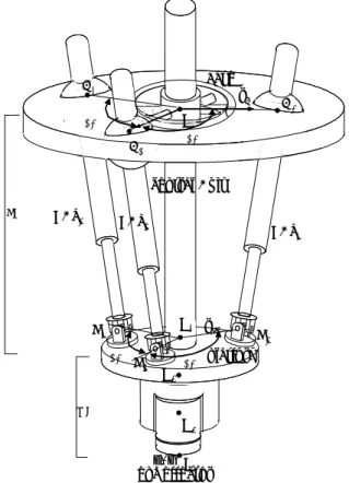
The PMWM Robot is made up of a PM generating the positional workspace and the WM generating the orientational workspace as shown in Fig. 1. The PM with linear actuation places a movable platform (platform) at a desired position by three linear actuators (LA_i, i=1,2,3) attached to a stationary base (base). Linear actuators, LA_i for i=1,2,3, are attached to B_i through spherical joints and connected to Pi through universal joints establishing link trains, which joint variables are represented by θij for j=1,2,..,6 (see Fig.2). Five rotary
joints are passive but only one prismatic joint is active to extend or shorten the length of a linear actuator. Points Bi and Pi for i=1,2,3, are affixed symmetrically 120° apart to the base and the platform, respectively, with ||O0Bi|| =rB , ||O3Pi||=rP. Points Oi for i=0,3 are the central points of the base and the platform, respectively. Purpose of a central axis, possessing one prismatic and two universal joints (see Fig. 2), is to constrain the PM permitting its d.o.f., i.e., three in the PM. Adding the WM with three rotary actuator on the p l a t f o r m m a k e s t h e P M W M t o h a v e s i x d . o . f . . O O6 central Axis O4 O5 platform base B1 B2 B3 120 ' rB PM 120' O3 rP1 end-effector 120'P 120 ' 1 P2 P3 WM O0 LA_2 LA_ 1 LA_ 3 O {6}
Fig. 1 PMWM Robot Manipulator
Study on Development of a machining robot using Parallel mechanism
Kun-Woo Park *, Tae_Sung Kim*, Min-Ki Lee* and Jin-Ho Kyung
*** School of Mechatronic Engineering, Changwon Nat’l University, Changwon, Korea (Tel : +82-55-275-7553; E-mail: kwoopark@sarim.changwon.ac.kr)
** Robot & Control Group, Intelligence & Precision Machine Dept.,Korea Institute of Macinery and Materials,171, Jang-dong, Yusong-gu, Daejeon
(Tel : +82-42-868-7885; E-mail: jhkyung@kimm.kre.kr)
Abstract:
This research develops the robot for the machining work. For machining work(cutting, milling, grilling, etc.), a robot manipulator is constructed by combining a parallel and a serial mechanism to increase stiffness as well as enlarge workspace. Based on the geometric constraints, this paper develops the formulation for inverse/direct kinematics and Jacobian to design and control a robot. Workspace is also analyzed to prove the advantage of the proposed robot.
θi5 θi6 platform θi4 θi2 θi1 θi3 θ3 θ6 O6 spline shaft ^ X6 ^ Y6 ^Z 6 θ2 θ1 θ5 θ4 O4 O5 ^ X5 ^ Y5 Z^5 ^ X4 ^ Y4 ^Z4 ^ Y0 ^ X0 ^ Z0 base platform O0 base Linear Actuator µ1 µ2 µ3 {0} {4} O3 ^ Y3 Z^ 3 ^ X3 µ4 µ5 µ6 {3} {5} {6}
Fig.2 linear actuator and Central axis
3. Kinematics, Jacobian and Workspace Analysis of
PMWM
3.1 Kinematics Analysis
Inverse kinematics of the PMWM is formulated to find active joint displacements for a given pose ( a position and orientation) of tool. As shown in Fig. 2, frames {0} assigned to the base, {3} and {4} to platform, and {5} and {6} to the WM and tool, with their origins at Oi for i=0,3,4,5,6: the z-axis of frame {0}, Zo, is downward being perpendicular to the base, the x-axis, Xo, is aligned with µ1, and the y-axis, Yo, is determined by a right hand rule, and the other three axes, Zi, Yi, Zi for i=4,5,6, are the same directions as those of the frame {0} at a zero position, i.e., θi =0 for i=1,2,..,6.
When the position vector from point O0 to O6, O0O6 , and the orientation of frame {6} with respect to {0}, 0 6
R , are given, θi for i=1,2,..,6 can be calculated by the following equations : [θ1 θ2 θ3 θ4 θ5 θ6 ] T = Kc−1(O0O6, 6 0 R ) (1) where −1 c
K () is the inverse kinematics function of the central axis similar to a serial robot. θ1,θ2 and θ3 are passive joints generating by three active joint θi3 of each LA_i. For the closed loops O0Bi Pi O3 for i=1,2,3 in the PM, BiPi, is described by θi1, θi2 and θi3, O0O3 and 3
0
R are represented by θ1,θ2 and θ3. Referring to (1), we have
||BiPi||= ||O0O3 - O0Bi+0R3
i
P
O3 || (i=1, 2, 3) (2).
The direct kinematics is formulated to find a pose (a position
and orientation) of tool for a given active joint displacements. Since the equations (2) are expressed in implicit forms, θi for i=1, .. , 6are obtained by Newton's numerical method. 3.2 Jacobian
For the fully parallel mechanism, Stewart-Gough platform, the Jacobian mapping 6×1 velocities of tool to six active joints velocities can be derived using screw theory or Plucker coordinate[5].
However these cannot be directly applied to the PMWM since velocities are separately generated by the PM and the WM. Instead, in this paper we use a motor vector defined by the relationship between the velocity of a joint and the resultant velocity of the platform.
If the velocity of point "o" in the platform is [Ω V]T generated by a unit velocity of joint θij, then a 6×1 motor vector is defined as
Mij = [Ω V]T.
From the motor algebra [6], a velocity of platform, Vplatform can be expressed by a linear combination of motors in link trains:
platform
V =
θ
&i1Mi1+θ
&i2Mi2+ … +θ
&ikMik (i = 1,...n) (3) where n and k is the number of link train and joint, respectively.For six joints of a central axis and WM, velocity of tool,
6 O V , is 6 O
V =
θ
&1Mc1+θ
&2Mc2+…+θ
&6Mc6 (4)where Mci(i=1,...,6) is a motor vector between tool and joints of central axis. Form equ. (4), if a given velocity of tool,
6 O V , we can get Θ& = −1 c J 1 6 O V (5) where Jc=[Mc1 Mc2… Mc6]T, Θ&=[
θ
&1θ
&2θ
&3θ
&4θ
&5θ
&6]T. Velocities
θ
&4,θ
&5 andθ
&6 are directly controlled by the active rotary joint of WM butθ
&1,θ
&2 andθ
&3must be indirectly generated by three active joints of LA_i of PM. To compute active joints velocities of LA_i, the velocity of point "O4" in the platform is calculated by following equation:4 O V =
θ
&1 4 1 c OM + 2θ
& 4 2 c OM + 3θ
& 4 3 c OM (6)where O4Mci (i=1, 2, 3) is a 6×1 motor vector between O4
and joint θi. From equ. (6), we can get
4 O V = O4Jc Θ&c (7) where O4Jc=[ 1 4 c O M 2 4 c OM 3 4 c OM ]T, c
Θ& =[
θ
&1θ
&2θ
&3]T. For a given,4
O
V a set of joint rates of ith active link train is acquired by
[
θ
&i1θ
&i2…θ
&i6]T= 4 −1i O J VO4 (8) where O4Ji =[ 1 4 i OM 2 4 i OM … 6 4 i OM ]T (i = 1,2,3) is motor vector between O4 and θij of the LA_i.
If 4 −1 i OJ =[ 1 i S Si2 …Si6]
T, velocities of active joints,
3 i
θ
& , is 3 iθ
& = Si3VO4 (9)Combining (6), (8) and (9) yields [
θ
&13θ
&23θ
&33θ
&4θ
&5θ
&6]T=AB −1c
J
6
O
V (10) where A and B are 6×21 and 21×6 matrices, respectively, as shown following : A= 1 1 0 1 0 33 23 13 S S S ,B= 1 1 0 1 0 3 2 1 4 4 4 c O c O c O M M M
Therefore, a 6×6 Jacobian matrix is J = A B −1
c
J (11) Based on the virtual work principle, the Jacobian with respect to linear actuators and force/moment is
= 6 1 τ τ M T J N F (12)
where F and N are the force and moment of the tool, and τi(i=1,..,6) is motor torques of linear actuators and rotary actuators.
In this paper, we apply the Jacobian for velocity control and singularity analysis.
3.3 Workspace Analysis
The workspace is decoupled into two: One is the positional workspace generated by the PM and the other is the orientational workspace by the WM. The orientational workspace is directly generated by three active joints on the WM. However, the positional workspace is complicated by being generated by three LA_i and a central axis. This paper analyzes only positional workspace.
The positional workspace is formed by the trajectory described by point O3 on the platform, when LA_i for i=1, 2, 3, with minimum or maximum extension, are rotated about their fixed joint-located at point Bi. With {x,y,z}T=O0O3, {x0i, y0i, z0i}T=O0Bi-0R3O3Pi" , From equ. (2),
θ
i23 is written as2 3
i
θ
=(x-x0i)2+(y-y0i)2+(z-z0i)2 ( i=1, 2 ,3) (13) When LA_imin≤θ
i23≤LA_imax, substituting the minimum andthe maximum lengths into (13) gives the concentric spheres of radii LA_imin and LA_imax, respectively. The workspace in 3D Cartesian space can be described as the intersection of three regions. Using the method addressed by Gosselin [7], we dissect the workspace volume into sections.
4. CONSTRUCT OF THE PMWM
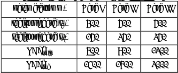
We design the PMWM which has a desired Ф600-400H (mm) cylindrical workspace and has simultaneously not singular points into workspace using analysis of kinematics, Jacobian, and workspace for three cases shown as Table I.
If the initial configuration of the PMWM has the base and the platform perpendicular to WM, i.e., θ4=0, the Jacobian is not invertible and singularity, i.e., det(J)=0. To avoid singularity, we have setting initial configuration at which the base and the WM have -45˚and 0˚ about the working plain, respectively, i.e., θ4 =45, shown as Fig. 3.
Table I. Design parameters of the PMWM robot
parameters(mm) Case I Case II Case III
radius of base(rB) 300 500 500
radius of base(rP) 150 250 250
LA_imin 600 900 1200
LA_imax 1400 1700 2000
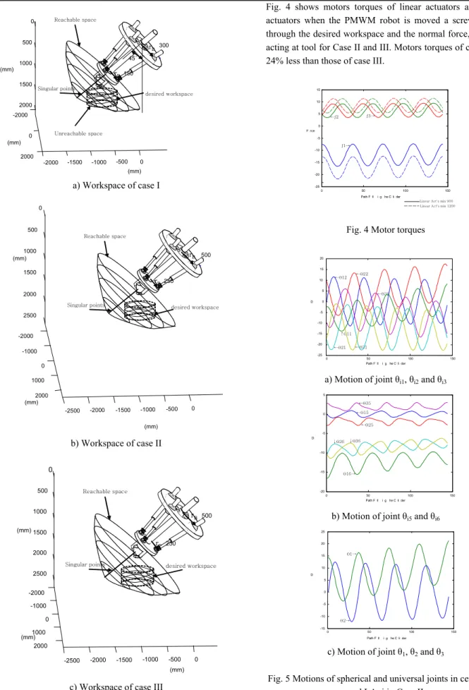
Fig. 3 shows the positional workspace of the PMWM with singularity points. Both case II and case III meet the desired workspace but case I does not because of unreachable space.
=300 rB rP=150 -2000 -1500 -1000 -500 0 2000 0 -2000 2000 1500 1000 500 0 Y(mm) X(mm) Z(mm) Reachable space Unreachable space Singular points 45˚ desired workspace a) Workspace of case I -2500 -2000 -1500 -1000 -500 0 -2000 -1000 0 1000 2000 2500 2000 1500 1000 500 0 X(mm) Y(mm) Z(mm) rB rP =500 =250 Reachable space
Singular points desired workspace
b) Workspace of case II X(mm) Y(mm) Z(mm) rB rP =500 =250 -2500 -2000 -1500 -1000 -500 0 2000 1000 0 -1000 -2000 2500 2000 1500 1000 500 0 Reachable space
Singular points desired workspace
c) Workspace of case III Fig. 3 Results of workspace analysis
Fig. 4 shows motors torques of linear actuators and rotary actuators when the PMWM robot is moved a screw motion through the desired workspace and the normal force, 10kN, is acting at tool for Case II and III. Motors torques of case II are 24% less than those of case III.
0 50 100 150 -25 -20 -15 -10 -5 0 5 10 15
Path Following The Cylinder Force
ƒ1→ ←ƒ2 ƒ3→
Linear Act’s min 900 Linear Act’s min 1200
Fig. 4 Motor torques
←θ12 ←θ22 ←θ32 ←θ21 ←θ31 ↑θ11 0 50 100 150 -25 -20 -15 -10 -5 0 5 10 15 20
Path Following The Cylinder DEG
a) Motion of joint θi1, θi2 and θi3
θ16→ ←θ15 ←θ35 ←θ25 ↓θ36 ↓θ26 0 50 100 150 -20 -15 -10 -5 0 5
Path Following The Cylinder DEG
b) Motion of joint θi5 and θi6
θ1→ θ2→ 0 50 100 150 -15 -10 -5 0 5 10 15 20 25
Path Following The Cylinder DEG
c) Motion of joint θ1, θ2 and θ3
Fig. 5 Motions of spherical and universal joints in central axis and LA_i in Case II
desired workspace, Fig. 5 shows that motions of spherical and universal joints in PM are -25˚ 25˚.
At the results we choose design parameters for the PMWM robot, as shown in Table II.
Table II. Spec. of Central Axis, Linear actuator and Joints for the PMWM robot parameters Spec. radius of base(rB) 500mm radius of base(rP) 250mm LA_imin 900mm LA_imax 1700mm
Stroke of linear actuator 800mm
Ranges of joint θi1, θi2 and θi3 -25˚ 25˚
Ranges of joint θi5 and θi6 -20˚ 20˚
Ranges of joint θ1, θ2 and θ3 -25˚ 25˚
5. CONCLUSION
This paper designs the PMWM robot for the machining work. The proposed PMWM is consisted of PM and WM generating a positional and orientational workspace, respectively. The PMWM has some advantages of follows: 1) The PM has a high stiffness standing a payload. 2) The WM has a large orientational workspace
3) The PMWM has a central axis constraining the PM permit- ing its d.o.f.
To design the proposed PMWM robot, we computed kinematics, Jacobian and workspace to decide specifications of a central axis, linear actuators and joints which meet the desired workspace and avoid the singularity into workspace. In future, we will study on the optimal design and dynamic analysis included gravity, inertial loads and payloads.
ACKNOWLEDGMENTS
This work was supported by the Gyeongnam Technopark and the Ministry of Commerce, Industry and Energy (MOCIE), Korea.
REFERENCES
[1] D. Stewart, "A platform with six degrees of freedom," in Proc. Inst. Mech. Eng., vol. 180, part 1, no. 5, 1965-1966, pp. 371-386.
[2] F. Pierrot, P. Dauchez and A. Fournier, Fast parallel robots. Journal of Robotic Systems, 8(6), pp. 829-840, 1991.
[3] M. Honegger, A. Codourey, and E. Burdet, "Adaptive control of the Hexaglide, a 6 dof parallel manipulator," IEEE int. Conf. on Robotics and Automation, pp. 543-548, Albuquerque, April, 21-28, 1997.
[4] J. Kim and F. C. Park, "Eclipse, A new parallel mechanism prototype," Position paper in Proceedings of the First European-Americna Forum on Parallel Kinematic Machines, Milan, Italy, August 31-September 1, 1998.
[5] E. F. Fichter, "A Stewart Platform-Based Manipulator: General Theory and Practical Construction", Int. J. Robot. Res., vol. 5, pp. 157-182, 1986.
[6] K. Sugimoto, "Kinematic and Dynamic Analysis of Parallel Manipulators by Means of Motor Algebra", ASME J. Mechanisms, Transmission, and Automation in Design, vol. 109, pp. 3-7, Mar, 1987.
[7] C. M. Gosselin, "Determination of the workspace of 6-dof parallel manipulators". ASME J. Mech. Design, vol. 112, pp. 331-336, 1990.