A Dissertation for the Degree of Doctor of Philosophy
Development of a rotary pump using the rotational clap
mechanism
회전 클랩 기구를 이용한 로터리 펌프 개발에 관한 연구
February 2016
SungBo Shim
Major of Biosystems Engineering
Department of Biosystems & Biomaterials Science and Engineering
Development of a rotary pump using the rotational
clap mechanism
지도교수 김 경 욱
이 논문을 공학박사 학위논문으로 제출함
2016년 2월
서울대학교 대학원
바이오시스템·소재학부 바이오시스템공학전공
심 성 보
심성보의 박사 학위논문을 인준함
2016년 2월
위 원 장
(인)
부위원장
(인)
위 원
(인)
위 원
(인)
위 원
(인)
A Dissertation for the Degree of Doctor of Philosophy
Development of a rotary pump using the rotational
clap mechanism
February 2016
By
SungBo Shim
Major of Biosystems Engineering
Department of Biosystems & Biomaterials Science and Engineering
Development of a rotary pump using the rotational
clap mechanism
SungBo Shim
Abstract
To avoid problems of the slider-crank mechanism, many attempts have been made to develop rotary-type machines. Nevertheless, none of them were practically successful except the Wankel engine, mainly due to poor sealing and manufacturing techniques. Furthermore, their theoretical analyses have not been advanced, and it still remains as just an idea or kinematic analysis stage. As technology has recently enough to solve the problems associated with the rotary-type machines, they have attracted attentions again.
In this study, the rotational clap mechanism that was first presented by Kim was improved, detailed mechanisms to realize the mechanism was developed, and the characteristics analysis and performance prediction of the rotational clap pump were conducted based on a prototype pump and its verification test.
A working principle of the mechanism and its design parameters were introduced with kinematic analysis of the pins and rotors. The vector equations developed in the analysis can be used to easily depict the motion characteristics of the mechanism for different design parameters. The inter-relationships between the design parameters were also examined to determine the proper crank radius and pin
distance within the allowable number of gear teeth and rotor size. The thickness angle of the jaw and inner radius of the rotor were found to be most significant constraints that affect the crank radius and pin distance of the mechanism.
The pressure, driving torque, and efficiency characteristics of the pump were evaluated to analyze the fundamental performance of the pump. The design constraints of the fixed internal gear and gear of shaft link using involute curves were examined, and the strength of the main components was designed.
The involute-type internal gear has design limits caused by three kinds of interferences. The kinematic constraints can aggravate this limits. As a result, designing a pump for high-pressure and low flow rate conditions with an involute-type internal gear can be difficult.
To verify the fundamental performances of this pump, a prototype pump was manufactured, and pump test equipment was installed. The simulated data of the flow rate, differential pressure, driving torque, and efficiencies were verified by comparison with experimental data.
The main parameters that affected the pump performance were the clearance between the rotor jaws and chambers, the number of jaws, the jaw width, and the jaw height. Therefore, the parameter studies that affect the pump performance were conducted, and the performance was then predicted under these conditions.
In these analysis results, the rotational clap mechanism can be realized as a pumping device on equal performance with conventional rotary pumps. In addition, It can have compact size, be good in a state of high viscosity and shear sensitive fluid, high flow rate, and works well with less vibration and power loss.
Keywords: Rotary pump, rotational clap mechanism, Pump performance, Pump
efficiency, Pump slip, low shear pump.
TABLE OF CONTENTS
1. Introduction ··· 1
2. Literature review ··· 3
3. Rotational clap mechanism ··· 5
3.1. Description of mechanism ··· 5
3.2. Kinematic analysis ··· 7
3.2.1. Displacement ··· 7 3.2.2. Velocity ··· 17 3.2.3. Accelerations ··· 203.3. Mechanism parameters ··· 23
3.3.1. Driving link ··· 23 3.3.2. Rotor ··· 243.4. Performance characteristics ··· 26
3.4.1. Performance parameters ··· 26 3.4.2. Interrelations of parameters ··· 27 3.4.3. Performance characteristics ··· 323.5. Conclusions ··· 34
4. Pump performance analysis ··· 35
4.1. Introduction ··· 35
4.2. Pressure analysis ··· 36
4.2.1. Assumptions ··· 36
4.2.2.1. Pressure head due to friction ··· 36
4.2.2.2. Pressure head due to mass acceleration ··· 37
4.2.2.3. Pressure head due to piping components ··· 37
4.2.2.4. Pressure head due to gravity ··· 38
4.2.2.5. Total head ··· 38
4.2.3. Pressure analysis in clap pump ··· 39
4.3. Forces and driving torque analysis ··· 42
4.3.1. Forces and driving torque calculation ··· 42
4.3.2. Parametric study ··· 49
4.4. Pump performance analysis ··· 56
4.4.1. Theory of pump performance ··· 56
4.4.1.1. Fundamental theory for the pump performance ··· 56
4.4.1.2. Theory of pump slip and forces caused by fluid viscosity ··· 57
4.4.1.3. Theory of efficiency for conventional positive-displacement pump ··· 62
4.4.2. Performance analysis for rotational clap pumps ··· 65
4.4.2.1. Analysis for slip and forces caused by fluid viscosity ··· 65
4.4.2.2. Efficiency analysis for rotational clap pump ··· 70
4.5. Conclusions ··· 71
5. Design of a prototype rotational clap pump ··· 73
5.1. Introduction ··· 73
5.2. Gear of the shaft link and fixed internal gear ··· 73
5.2.1. Geometric constraints ··· 73
5.2.1.1. Involute interference ··· 76
5.2.1.3. Trimming interference ··· 77
5.2.1.4. Case studies to avoid interferences in this pump ··· 78
5.2.2. Gear strength calculation for prototype pumps ··· 82
5.3. Crank ··· 89
5.3.1. Design for strength ··· 89
5.3.2. Design for stiffness ··· 98
5.4. Pins ··· 102
5.4.1. Design for strength ··· 102
5.5. Shaft link ··· 107
5.5.1. Design for strength ··· 107
5.5.2. Design for stiffness ··· 116
5.6. Conclusions ··· 118
6. Verification test ··· 119
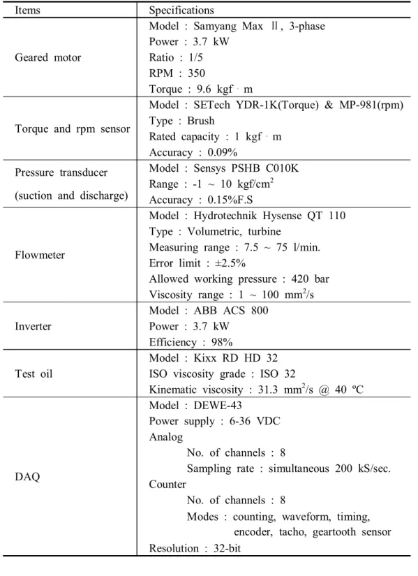
6.1. Prototype pump and test equipment ··· 119
6.2. Pressure analysis of the pump and piping system ··· 122
6.3. Verification ··· 124
6.3.1. Clearances calculation and validation of performance parameters when the throttle valve is fully open ··· 124
6.3.2. Pressure pulsation and cavitation ··· 135
6.3.2.1. Using multi-pumps ··· 135
6.3.2.2. Using a pulsation dampener ··· 137
6.4. Conclusions ··· 143
7. Performance prediction ··· 144
7.2. Parametric study ··· 144
7.3. Performance prediction ··· 147
7.4. Comparison among the conventional positive-displacement pumps and
the clap pump ··· 156
7.5. Conclusions ··· 159
8. Overall conclusions and further studies ··· 160
9. References ··· 162
Appendix A: Specifications of piping system for the pump ··· 166
Appendix B: Pump performance curves ··· 172
LIST OF TABLES
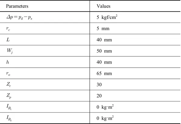
Table 4.1 Parameters involved in the parametric study ··· 50
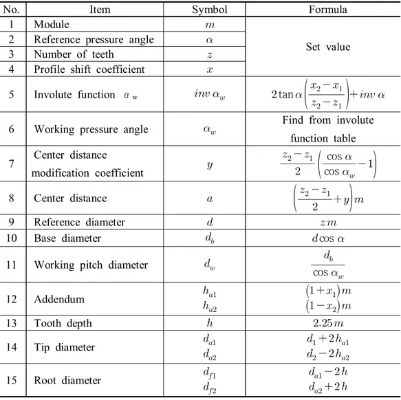
Table 5.1 Calculation of a profile-shifted internal gear and external gear when the center distance is not given (Kohara Gear Industry Co., Ltd., 2015). ··· 74
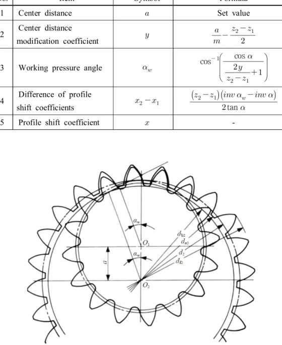
Table 5.2 Calculation of a profile-shifted internal gear and external gear when the center distance is given (Kohara Gear Industry Co., Ltd., 2015). ··· 75
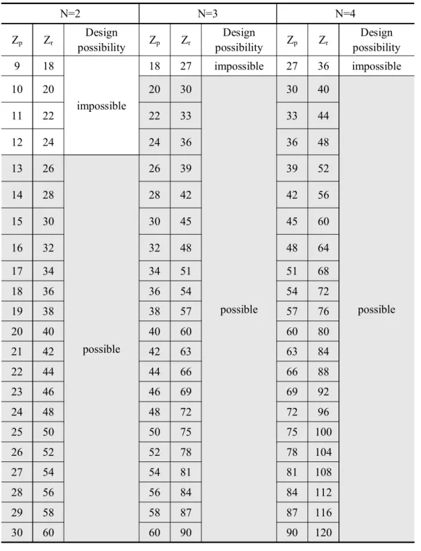
Table 5.3 Cases to prevent internal gear interference when gear module , center distance (=crank radius ), and reference pressure angle . ··· 79
Table 5.4 Cases to prevent internal gear interferences when gear module , and reference pressure angle . ··· 80
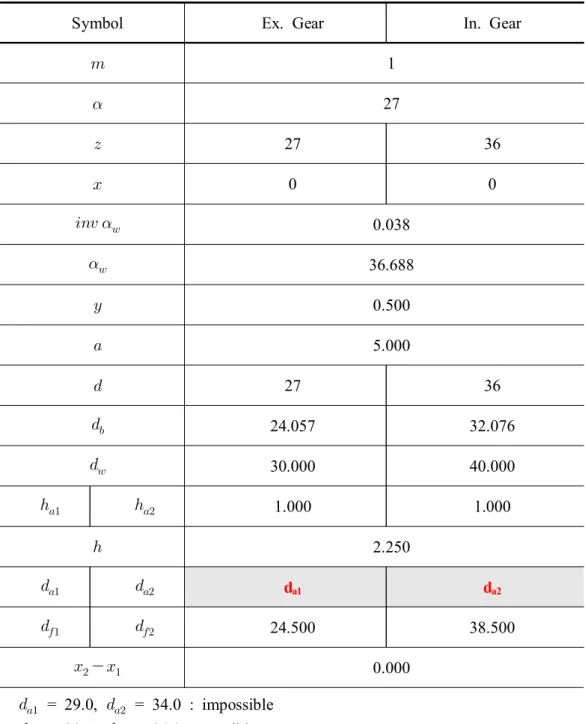
Table 5.5 Example of the effect of diameter of internal and external gears on interference. ··· 81
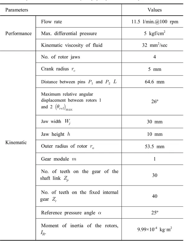
Table 5.6 Specifications of the clap pump used in performance test. ··· 86
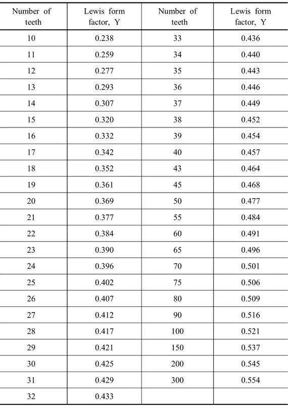
Table 5.7 Lewis form factor (Hong, 2013). ··· 88
Table 6.1 Specifications of the test equipment for the pump. ··· 121
Table 6.2 Loss coefficients for pipe components (Hydraulic Institute, 1990; E. S. Menon et al, 2010). ··· 123
Table 6.3 Percentage errors of the simulated suction pressure, discharge pressure, and driving torque at the primary frequency 5.5 Hz. ··· 131
Table 6.4 Effect of the number of pistons or rotor pairs on flow variation. ··· 136
Table 7.2 Characteristics of conventional positive-displacement pumps and clap pump ··· 158
LIST OF FIGURES
Fig.2.1. A patented rotational clap mechanism (Kim, 2011) ··· 4 Fig.3.1. Components of the rotational clap mechanism ··· 6 Fig.3.2. Motion of the pins relative to the center of rotor. ··· 9 Fig.3.3. Rotating radius of the pin when , , , and
. ··· 11 Fig.3.4 Relative angular displacement of the rotors, , when ,
, , and . ··· 14 Fig.3.5. Clearances angle between two adjacent jaws when ,
, , and . ··· 14 Fig.3.6. Sequence of suction and discharge motions by the clearance angle
between two adjacent jaws. ··· 15 Fig.3.7. Suction and discharge motions occuring simultaneously when the rotors
have 4 jaws ··· 16 Fig.3.8. Pin velocity when , , , , and
. ··· 19 Fig.3.9. Angular velocity of rotor when , , ,
, and . ··· 19 Fig.3.10. Pin accelerations when , , , ,
and . ··· 22 Fig.3.11. Angular acceleration of rotor when , , ,
Fig.3.12. Rotor parameters. ··· 25
Fig.3.13. Determination of the number of internal gear teeth and crank radius by the number of the gear teeth and rotor jaws. ··· 28
Fig.3.14. Combinations of the crank radius, number of rotor jaws and pin distance to make the thickness angle positive. ··· 30
Fig.3.15. Maximum rotating radius of the pin. ··· 31
Fig.3.16. Minimum rotating radius of the pin. ··· 31
Fig.3.17. Displacement of a clap mechanism having a jaw of 50 cm width and 40 cm height and a rotor of 65 cm outer radius. ··· 33
Fig.4.1. Fluid flow through a pipe. ··· 40
Fig.4.2. Fluid movement in the rotational clap mechanism. ··· 41
Fig.4.3. A schematic diagram of the fluid movement ··· 41
Fig.4.4 Direction changes in hydraulic forces acting on the rotors and the housing ··· 43
Fig.4.5 Free-body diagram for forces acting on the rotors, gear of the shaft link, internal gear and the crank. ··· 48
Fig.4.6 Rotor forces and . ··· 51
Fig.4.7 Pin forces and . ··· 51
Fig.4.8 Gear force . ··· 52
Fig.4.9 Driving torque . ··· 52
Fig.4.10 Driving torque vs. crank radius . ··· 53
Fig.4.11 Pin forces vs. crank radius . ··· 54
Fig.4.12 Gear forces vs. crank radius . ··· 55
Fig.4.13 Drag due to the viscosity of the liquid(Wilson, 1950). ··· 61
Fig.4.15 Wilson’s efficiency curve for a pump(Wilson, 1950). ··· 65
Fig.4.16 Jaw model simplified as a rectangle for the analysis of flow and torque losses. ··· 69
Fig.4.17 Flow losses in suction and discharge chamber of the pump. ··· 70
Fig.4.18 Force losses in suction and discharge chamber of the pump. ··· 70
Fig.5.1. Meshing of the internal gear and external gear(Kohara Gear Industry Co., Ltd., 2015). ··· 75
Fig.5.2. Forces acting on the gears ··· 87
Fig.5.3. Cantilever model of a gear tooth (Shigley and Mischke, 2001). ··· 87
Fig.5.4. Loads and dimensions for the main shaft of crank. ··· 92
Fig.5.5. Shear force acting on the crank shaft ··· 97
Fig.5.6. Bending Moment acting on the crank shaft ··· 97
Fig.5.7. Maximum deflection of the main shaft of the crank. ··· 101
Fig.5.8. Deflection of the main shaft of the crank. ··· 101
Fig.5.9. Loads acting on the pin. ··· 105
Fig.5.10. Shear force acting on the pin. ··· 106
Fig.5.11. Bending moment acting on the pin. ··· 106
Fig.5.12. Free-body diagram of forces acting on the shaft link ··· 111
Fig.5.13. Force components with respect to the xc'-yc'-zc' plane. ··· 112
Fig.5.14. Driving torque vs. the length of shaft link. ··· 114
Fig.5.15. Shear force vs. the length of shaft link. ··· 115
Fig.5.16. Bending moment vs. the length of shaft link. ··· 115
Fig.5.17. Parameters for the deflection of the shaft link. ··· 117
Fig.5.18. Deflection of the shaft link according to the length of the shaft. ··· 117
Fig.6.2. Second-order polynomial model representing the differential pressure vs. flow rate of a flowmeter (Hydrotechnik, 2015). ··· 124 Fig.6.3. Measured flow rate as a function of the crank speed with the throttle valve
fully opened. ··· 126 Fig.6.4. Comparison between the measured and simulated volumetric efficiency as a function of the crank speed when the clearances and were 0.2572 mm. ··· 126 Fig.6.5. Comparison between the simulated and measured flow rates in the time
domain. ··· 127 Fig.6.6. Comparison between the simulated and measured suction pressures in the
time domain. ··· 127 Fig.6.7. Comparison between the simulated and measured discharge pressures in the
time domain. ··· 128 Fig.6.8. Comparison between simulated and measured driving torque in time
domain. ··· 128 Fig.6.9. Comparison between the simulated and measured flow rates in the
frequency domain. ··· 129 Fig.6.10. Comparison between the simulated and measured suction pressures in the
frequency domain. ··· 129 Fig.6.11. Comparison between the simulated and measured discharge pressures in
the frequency domain. ··· 130 Fig.6.12. Comparison between the simulated and measured driving torque in the
frequency domain. ··· 130 Fig.6.13. Comparison between the measured and simulated pump efficiency as a
Fig.6.14. Measurement of the clearances with a feeler gauge. ··· 133
Fig.6.15. Measurement of the crank misalignment with a dial gauge. ··· 134
Fig.6.16. Fluctuation of friction torque caused by the crank misalignment ··· 134
Fig.6.17. Pulsation dampeners installed in the pump testing system. ··· 139
Fig.6.18. Effect of the pulsation dampener on flow variations. ··· 139
Fig.6.19. Effect of the pulsation dampener on discharge pressure variations. ··· 140
Fig.6.20. Comparison between measured and simulated p-Q curves when the crank speed was 100 rpm. ··· 140
Fig.6.21. Comparison between measured and simulated p-Q curves when the crank speed was 200 rpm. ··· 141
Fig.6.22. Comparison between measured and simulated p-Q curves when the crank speed was 300 rpm. ··· 141
Fig.6.23. Comparison between measured and simulated p-Q curves when the crank speed was 400 rpm. ··· 142
Fig.6.24. Comparison between measured and simulated p-Q curves when the crank speed was 500 rpm. ··· 142
Fig.7.1. Efficiency vs. clearance when n = 100 rpm, h = 10 mm, N = 4. ··· 145
Fig.7.2. Efficiency vs. jaw height when n = 100 rpm, = = 0.06 mm, and N = 4. ··· 146
Fig.7.3. Efficiency vs. number of jaws when n = 100 rpm, = = 0.06 mm, h = 10. ··· 146
Fig.7.4. Performance curves under the initial conditions (crank speed, n = 100 rpm). ··· 148 Fig.7.5. Pump efficiency as a function of under the initial conditions
(crank speed, n = 100 rpm). ··· 149 Fig.7.6. Performance curves under the second conditions (crank speed,
n = 100 rpm). ··· 150 Fig.7.7. Pump efficiency as a function of under the second conditions
(crank speed, n = 100 rpm). ··· 151 Fig.7.8. Volumetric efficiency before and after the parameter optimization
(crank speed, n = 100 rpm). ··· 152 Fig.7.9. Torque efficiency before and after the parameter optimization
(crank speed, n = 100 rpm). ··· 153 Fig.7.10. Pump efficiency before and after the parameter optimization
(crank speed, n = 100 rpm). ··· 153 Fig.7.11. Performance curves under the final conditions (crank speed,
n = 100 rpm). ··· 154 Fig.7.12. Pump efficiency as a function of under the final conditions
(crank speed, n = 100 rpm). ··· 155 Fig.7.13. Space between different types fo rotors and the housing ··· 157 Fig.A.1. The flow in sudden contraction and expansion pipe. ··· 167 Fig.A.2. Dimensions of , , , , , and . ··· 171 Fig.A.3. Dimensions of , , , and . ··· 171
Fig.A.4. Performance curve when =4, =100 rpm, ==0.06 m, =14 mm, and =20.72 mm. ··· 172 Fig.A.5. Performance curve when =4, =300 rpm, ==0.06 m, =14 mm,
Fig.A.6. Performance curve when =4, =500 rpm, ==0.06 m, =14 mm, and =20.72 mm. ··· 174 Fig.A.7. Performance curve when =4, =750 rpm, ==0.06 m, =14 mm,
and =20.72 mm. ··· 175 Fig.A.8. Performance curve when =4, =1000 rpm, ==0.06 m, =14 mm,
and =20.72 mm. ··· 176 Fig.A.9. Comparison between flow rate vs pressure curves according to crank
speed. ··· 177 Fig.A.10. Comparison between volumetric efficiency vs pressure curves according to crank speed. ··· 177 Fig.A.11. Comparison between torque efficiency vs pressure curves according to
crank speed. ··· 178 Fig.A.12. Comparison between overall efficiency vs pressure curves according to
1. Introduction
Conventional rotary pumps intakes the fluid through the clearance between the rotating elements and pump housing and force it to move along the way to discharge out of the pump. Advantages of the rotary pump include self-priming, relatively smooth discharging and delivering fluid to high pressure. However, it has also have disadvantages such as small displacement, excessive wear due to erosion which are caused by the small clearance between the rotating elements and the pump housing, etc.
Slider-crank mechanism has been widely used in many types of plunger and piston pumps. They have also problems of high level of vibration and power losses due to excessive friction between the reciprocating piston and pump housing as the pump speed increases. To avoid such problems of the slider-crank mechanism, many attempts have been made to develop rotary-type machines (Deng et al. 2013; Fedorovich. 2006; Librovih. 2003; Librovich. 2004; Masmi Sakita. 2006; Morgado. 2004; Shih. 1993a; Shih. 1993b; Xu. 2014). Nevertheless, their theoretical analyses have not been advanced, and it still remains as just an idea or kinematic analysis stage. Furthermore, none of them were practically successful except the Wankel engine, mainly due to poor sealing and manufacturing techniques.
As technology has recently enough to solve the problems associated with the rotary-type machines, they have attracted attentions again.
This study also attempted to avoid problems of the reciprocating slider-crank mechanism, which has been used in many positive-displacement pumps, as a pumping device using a rotational clap mechanism that was first presented by Kim (Kim, 2011; Kim 2012), because the rotational clap mechanism is one of the most
simple rotary mechanism to realize a pumping device. It can increase the displacement and works well with less vibration and power loss although the pumping speed increases.
Research objectives
The detailed mechanisms to realize the rotational clap mechanism presented by Kim (Kim, 2011; Kim, 2012) have some problems for application to a pump. Therefore, the objectives of this study were to improve the rotational clap mechanism, develop a detailed mechanism, and conduct the characteristics analysis and performance prediction of a rotary pump using the advanced rotational clap mechanism. Details of the objectives are as follows:
1. To improve and develop for the detailed mechanism based on analysis of the basic mechanism,
2. To do kinematic analysis of the rotational clap mechanism so that the theoretical basis of its working principle, motions, and performance characteristics can be founded,
3. To develop a computer model to simulate the pressure, torque, flow rate, and efficiency of the pump when the rotational clap mechanism is used as a pumping device including prototype testings for the model verification,
4. To standardize the design process of the mechanism components based on the prototype pump design,
5. To investigate the effects of the design parameters and their constraints of the mechanism on its performance,
6. To predict the pump performance under the given condition, and compare among the conventional positive-displacement pumps and clap pump.
2. Literature review
In the late 19th century, Reuleaux(1876) already introduced various types of rotary machines in his book. However, the Wankel engine is only one that has been commercialized successfully. Main obstacle was lack of technology to solve the problems of poor sealing and manufacturing. Since he introduced the Wankel engine in 1954, much research has been conducted on the Wankel engine. Yamamoto (1981) has reviewed the history of rotary engine development from the late 16th to the late 19th centuries and classified the rotary engines into three different types: single rotating, oscillatory rotating, and planetary rotating engines. Hege (2006) also has summarized many endeavors for the commercialization of Wankel engines conducted in automobile companies from 1957 to 2000.
Advances in the sealing technology has made the commercialization of the Wankel engines possible. Performance improvement of other types of rotary machines may also be attributable to such advances.
Murphy (2012) introduced a number of rotary machines and their characteristics in his master's thesis. Shih (1993a; 1993b) analyzed the kinematics of the cycloidal internal combustion engine mechanism and compared the epicycloidal and hypocycloidal internal combustion engine mechanisms. Librovich (2003; 2004) presented the basic structure and work principles of the rotary vane engine (RVE) based on the Kauertz-Virmel-type rotary combustion engine along with the analysis, design, and modeling of a rotary vane engine. Hao Deng et al (2013), Masmi Sakita (2006), and Xu (2014) also conducted studies on the fundamental principles and its characteristics. Among these ideas, the closest to commercialization were those of Morgado (2004) and Fedorovich (2007). However, they have mainly
focused on the rotary engines. Few works have been made for the rotary pumps. Kim (2011 and 2012) first presented the rotational clap mechanism in his patents. The mechanism is comprised of a cylindrical housing, a crank shaft, a crank pin, a internal gear, connecting rods and rotational pins, a external gear attached on the end of connecting shaft, and a pair of rotary pistons with several wings (see fig.2.1). A pair of rotary pistons that are driven at different angular velocities caused by the relative motions among the crankshaft, internal gear, and external gear make the clearance between the wings. This clearance results in suction and discharge motions. He insisted that the advantages of this mechanism are the high volumetric efficiency, small size, low weight, and low noise.
3. Rotational clap mechanism
3.1. Description of mechanism
The rotational clap mechanism is a five-link spatial mechanism which comprises of a crank as the driving link, a shaft link having two pins symmetrically located in opposite direction at a plate rigidly mounted on its middle and two gears rigidly attached to both ends, two rotors with jaws equally spaced along their circumferences and a fixed internal gear. The width of jaw is extended unilaterally twice of the rotor width so that the two rotors jaws can be engaged completely. Fig.3.1 illustrates the linkages of the mechanism. As the crank rotates, the gear pin-jointed to the crank rotates about the crank pin and at the same time about the center of the fixed internal gear, making the motions of a hypo-cyclic gear train. The shaft link also can rotate about the crank pin and about the center of the fixed internal gear at the same time. This motion of the shaft link makes the pins rotate about the center of the fixed internal gear with a periodically-varying radius. The rotors are driven by the pins on the shaft link through a pin-in-slot joint where the pins move along a radial slot on the contacting faces of two rotors. Since the rotational radius of the pin changes as the crank rotates at a constant velocity, angular velocities of the two rotors also change accordingly. The relative velocity between the two rotors makes one rotor lead and lag periodically with respect to the other. These lead and lag motions result in a continuous cycle of approach-contact-recess of two adjacent rotor jaws similar to a hand clapping from which the mechanism is named. The continuous lead and lag motions can be used for the suction and discharge motions required for pumping.
3.2. Kinematic analysis
3.2.1. Displacement
Let O-X-Y be a rectangular coordinate with positive x axis to the right, y axis upwards, and its origin at the center of rotors, which also coincides with the center of the fixed internal gear. As the crank rotates counter-clockwise as shown in fig.3.2, the pin-jointed gear rotates clockwise with respect to the crank pin and at the same time rotates counter-clockwise about the center of the fixed internal gear. Then, absolute angular displacement of the gear can be expressed as equation (3.1). Let the pins on the shaft link be designated as and respectively. Then the position vector equations for the pins can be expressed as equations (3.2) and (3.3) respectively.
(3.1) (3.2) (3.3)where, = absolute angular displacement of the gear
= number of teeth on the fixed internal gear
= number of teeth on the gear of the shaft link
= crank radius
= distance between pins and
= radius of pin with respect to the center of rotor O
= radius of pin with respect to the center of rotor O
= angular displacement of vector
= angular displacement of vector
It should be noted that the pins on the shaft link rotate negatively clockwise about the center of the rotors as the crank rotates positively counter-clockwise. In other words, is positive while ,
and are all negative in equations (3.2) and (3.3).
Substituting equation (3.1) into equation (3.2) and separating the real and imaginary parts of equation (3.2) yields,
cos
cos (3.4) sin
sin (3.5) solving for yields,
cos (3.6)For the clap mechanism to make one complete cycle, the gear on the shaft link must rotate through in clockwise and the crank accordingly in count-clockwise through an angle of
radians. Therefore,
can be
expressed as equation (3.7-a) for the first half of the cycle and as equation (3.7-b) for the second half. That is
when ≤ ≤ cos
cos
(3.7-a) when ≤ cos
cos
(3.7-b)Similarly, solving equation (3.3) for
and yields,
cos (3.8) when ≤ ≤ cos
cos
(3.9-a)when ≤ cos
cos
(3.9-b)As the crank rotates with a constant angular velocity, the pins are constrained to move along the radial slots on the rotors and at the same time rotate about the center of the rotors with radii of
and varying periodically with a period of
as shown in fig.3.3. It is also noted from fig.3.3 that
decreases as
increases and
is a minimum when is a maximum, and vice versa.
Fig.3.3. Rotating radius of the pin when , , , and
.
be formed by every two adjacent jaws and the rotor housing. The volume of the clearance varies with the relative angular displacement of the two rotors, which
also varies with a period of
as shown in fig.3.4 and determined as
(3.10)
Then, as the crank rotates, the clearance angles in front and back of a jaw can be expressed respectively as follows:
max (3.11)
max (3.12)Fig. 3.5 shows the front and back clearance angles as a function of crank angle. It is noted from fig.3.5 that the clearance angle varies with a period of
so that when two adjacent jaws are in contact, the clearances in the front and back of the two jaws in contact reach the maximum. Therefore, the maximum values of and are given as
max
max
max
max (3.13)
max
max
max
max (3.14)As the clearance angle increases from zero to a maximum, a suction motion occurs between the two adjacent jaws while it decreases from a maximum to zero, a
discharge motion occurs. These suction and discharge motions occur as many time as the number of clearances that can be formed by the rotors during a period of
. Fig. 3.6 illustrates a sequence of the suction and discharge motions that can be developed during one complete cycle of a rotational clap mechanism having 3-jaw rotors ( ), 20-tooth gear ( ) and 30-tooth internal gear ( ). Fig.3.4 shows that the two rotors come into contact at crank angles of
, ⋯. At these crank angles,
and becomes equal,
that is,
cos
(3.15)
cos
(3.16) and between and becomes cos cos (3.17)Then,
max can be obtained as follows as depicted in fig.3.2:
max cos
Fig.3.4 Relative angular displacement of the rotors when ,
, , and .
Fig.3.5. Clearances angle between two adjacent jaws when ,
Fig.3.6. Sequence of suction and discharge motions by the clearance angle between two adjacent jaws.
Fig.3.7. Suction and discharge motions occurring simultaneously when the rotors have 4 jaws.
3.2.2. Velocity
As the crank rotates with a constant angular velocity the absolute angular velocity of the gear on the shaft link is obtained by taking time derivative of equation (3.1) as follows:
(3.19)Differentiating the position vector equation (3.2) with respect to time yields
(3.20)
Equation (3.20) can be resolved into two equations (3.21) and (3.22) by equating the real and imaginary parts. That is
sin sin cos sin (3.21) cos cos sin cos (3.22)
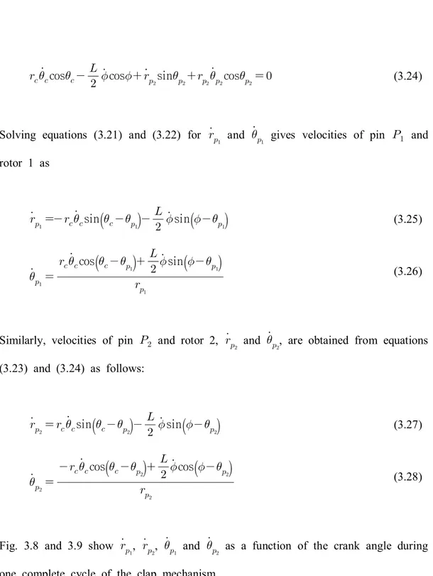
Similarly, following equations can be obtained from equation (3.3).
sin
sin
cos
cos
sin cos (3.24)
Solving equations (3.21) and (3.22) for
and gives velocities of pin and
rotor 1 as sin
sin
(3.25) cos
sin
(3.26)Similarly, velocities of pin and rotor 2,
and , are obtained from equations
(3.23) and (3.24) as follows: sin
sin
(3.27) cos
cos
(3.28)Fig. 3.8 and 3.9 show
, , and as a function of the crank angle during
Fig.3.8. Pin velocity when , , , , and .
Fig.3.9. Angular velocity of rotor when , , , , and .
3.2.3. Accelerations
Accelerations of the pin and rotor are obtained by taking time derivative of the velocity vector equations. Differentiating equations (3.25) and (3.26) with respect to time and equating the real and imaginary parts yield a set of two simultaneous equations. Solving these equations for
and gives the accelerations of pin
and rotor 1 as follows:
sin
sin
cos
cos
(3.29)
cos
cos
sin
sin
(3.30)Similarly, the accelerations of the pin and rotor 2,
and , can be obtained
from equations (3.27) and (3.28). That is
sin
sin
cos
cos
(3.31)
cos
cos
sin
sin
(3.32)It should be noted that the accelerations and become zero if the angular velocity of the crank is constant. Fig. 3.10 and 3.11 shows accelerations,
, ,
and as a function of the crank angle when the crank rotates with a constant
Fig.3.10. Pin accelerations when , , , and .
Fig.3.11. Angular acceleration of rotor when , , ,
3.3. Mechanism parameters
3.3.1. Driving link
Driving links of the rotational clap mechanism are those that drive the rotors. They includes the crank, the gears on the shaft link and the fixed internal gear. The parameters of those links are related to each other as follows:
(3.33)
where, = gear module
In addition to this relationship, the number of teeth on the gear in the shaft link and the fixed internal gear must satisfy the integer requirement that determines a relationship between the number of cycles for suction and discharge motions, and the working period of the mechanism. In other words, the frequency of the suction and discharge motions during a working cycle of the mechanism must be an integer to make the motions completed during the cycle. This relation can be expressed as follows: or (3.34)
This also determines the number of jaws to be mounted on the rotors, and the suction and discharge ports. Equations (3.33) and (3.34) are the relationships that the parameters of the driving links must satisfy.
3.3.2. Rotor
Rotor parameters are those that describe the configuration of the rotors. They include the inner diameter, outer diameter and width of the rotor, number of jaws, pitch angle, thickness angle, height and width of the jaw, and length of the slot which are illustrated in fig.3.12.
From equation (3.34), the number of jaws is determined as . Then, pitch angle of the jaw, , defined as an angle between the jaws is given by
(3.35)
To determine the thickness angle of the jaw, the maximum relative angular displacement between the rotors 1 and 2, that is,
max
max, must beknown. Let be the thickness angle of the jaw, then the maximum relative angular displacement can be expressed as
max
(3.36)
of the jaw yields
cos
(3.37)The inner radius of the rotor should be smaller than the minimum value of
or
and the outer radius larger than the maximum value of or , which all
depend on the values of and . The length of the slot, , on the rotor also depends on the values of and , and is given in equation form as follows
max
min
(3.38)The width of jaw should be determined as twice of the rotor width.
3.4. Performance characteristics
3.4.1. Performance parameters
Displacement and flow may be the most important parameters to evaluate the performance of the rotational clap mechanism as a pumping device. During the suction motion, the volume displaced by the two adjacent jaws can be expressed as
max(3.39)
where, = outer radius of the rotor
= jaw height
= jaw width
When the crank makes one complete revolution, the number of cycles for the suction and discharge motions become
. Therefore, the displacement of
the clap pump mechanism can be expressed by
max
(3.40)If the crank rotates at a constant angular velocity of rpm, the theoretical mean flow of the rotational clap pump can be calculated as follows:
max
(3.41)3.4.2. Interrelations of parameters
To investigate the performance characteristics of the rotational clap mechanism as a pumping device, the effects of some mechanism parameters on the displacement were investigated. As shown in equations (3.13), (3.18) and (3.40), displacement of the rotational clap mechanism is affected mainly by number of jaws, crank radius, pin distance, and number of teeth on the gears. However, since these parameters are inter-related each other, it is difficult to derive any unique effects of these parameters on the displacement.
From equations (3.33) and (3.34), the crank radius and number of the fixed internal gear teeth can be obtained from the number of the gear teeth on the shaft link and rotor jaws as shown in fig.3.13.
Another constraint to limit the crank radius is the thickness angle of the jaw. The thickness angle is affected by the crank radius, number of rotor jaws, and pin distance. Since the thickness angle should be positive and greater than a given value, the crank radius must be determined under such a constraint. fig.3.14 shows the positive thickness angles that can be obtained by the combinations of the crank radius, number of rotor jaws, and pin distance. It is noted from fig.3.14 that the crank radius must be reduced to have the positive thickness angle as the number of jaws increases. If necessary, the crank radius can be increased by increasing the pin distance. However, increasing the crank radius is limited because the thickness angle becomes negative as the crank radius increases no matter what value of the
pin distance is taken. Therefore, the crank radius must be determined to meet the lower limit value required to drive the mechanism taking the number of jaws and the pin distance into consideration.
Fig.3.13. Determination of the number of internal gear teeth and crank radius by the number of gear teeth and rotor jaws.
The crank radius and pin distance are also affected by the minimum and maximum radii of the pin rotation with respect to the center of the rotor, from which the inner and outer radii of the rotor can be determined. The maximum rotating radius of the pin increases with the crank radius and pin distance while the minimum rotating radius increases only with the pin distance but decreases with the crank radius as shown in figs.3.15 and 3.16. The maximum and minimum rotating radii of the pin also determine the length of the slot on the rotor face as shown in equation (3.38).
It should be noted that the inner radius of the rotor must be less than the minimum rotating radius of the pin while the outer radius needs to be greater than the maximum rotating radius.
Since the crank radius and pin distance are limited by the thickness angle of the jaw and the inner radius of the rotor, they must be determined within the allowable range taking the overall size of the clap mechanism. Once the crank radius and pin distance are determined, the number of gear teeth and its module can be determined accordingly using fig.3.13.
Fig.3.14. Combinations of the crank radius, number of rotor jaws and pin distance to make the thickness angle positive.
Fig.3.15. Maximum rotating radius of the pin.
3.4.3. Performance characteristics
Displacement of the clap mechanism varies with crank radius, pin distance, number of jaws, and jaw width and height. fig.3.17 shows the displacement of the mechanism when the width and height of jaw are kept constant with a rotor of 65 cm outer radius. Displacement increases with the crank radius at a given number of jaws and pin distance. However, at a given crank radius it increases with the number of jaws and decreases with the pin distance. Since the crank radius is limited as the number of jaws increase, displacement performance of the clap mechanism is also limited accordingly with number of jaws. However, it can be increased as much as possible by increasing the jaw width and height once the crank radius, pin distance and the number of jaws are determined since they are not inter-related with other parameters of the mechanism.
Fig.3.17. Displacement of a clap mechanism having a jaw of 50 cm width and 40 cm height and a rotor of 65 cm outer radius.
3.5. Conclusions
In this chapter, working principle of the rotational clap mechanism and its design parameters were introduced together with kinematic analysis for the pins and rotors. Vector equations developed for the analysis can be used to easily depict the motion characteristics of the mechanism by changing the design parameters. Inter- relationship between the design parameters was also presented to determine the proper crank radius and pin distance within the number of gear teeth and rotor size allowable for them. Thickness angle of the jaw and inner radius of the rotor were found to be most significant constraints affecting the crank radius and pin distance of the mechanism.
Displacement of the clap mechanism varies with crank radius, pin distance, number of jaws, jaw width and jaw height. It increases with the crank radius at a given number of jaws and pin distance while at a given crank radius it decreases with pin distance and increases with the number of jaws. However, the displacement can be increased as much as possible by increasing the jaw width and height once the crank radius, pin distance and the number of jaws are determined since they are not inter-related with other parameters of the mechanism.
Although there exit some limitations in its application due to constrains on the crank radius and pin distance, the rotational clap mechanism can be applied to a pumping device.
4. Pump performance analysis
4.1. Introduction
The fundamental factors to determine the pump performance are the pressure, flow rate, and efficiency. Therefore, in the case of a simple system, only the pressure and flow rate are represented on the performance curve. On the other hand, with a complex system, the performance curve must represent the efficiency, required power, and net positive suction head (NPSH) in addition to the flow rate and pressure. This is because other factors such as economic considerations and system safety may be more critical than the fundamental performance. A positive- displacement pump generates pressure pulsations, which can cause severe system safety and reliability problems and have a detrimental effect on the net positive suction head. Therefore, the pressure pulsation is an important factor that affects the performance of a positive-displacement pump.
A rotational clap pump was developed to convert the positive displacement reciprocating pump actions into a rotary mechanism. A previous chapter discussed the kinematic analysis and working principles of the rotational clap pump. The motion analysis, inter-relationships of design parameters, inherent constraints, and performance characteristics of the rotational clap mechanism as a pumping device were described.
This chapter presents the pressure, driving torque, and efficiency characteristics of a rotational clap pump for analysis of its fundamental performance.
4.2. Pressure analysis
4.2.1. Assumptions
Pressure and its pulsation in this pump were analyzed on the basis of the following assumptions:
∙ Incompressible flow.
∙ Ignoring the elasticity of the piping system. ∙ Pressure is the same in control volume.
∙ Each flow space in the pump is modified with the circular pipe.
4.2.2. Pressure head
Pressure is required to pump the liquid through the system for a given flow rate. A sufficiently high pressure is required to overcome the internal resistance of the system, which is also known as head. The total head is the sum of individual heads as follows:
4.2.2.1. Pressure head due to friction
Pressure head from flow friction in a pipe is given by the well-known Darcy equation. It can be expressed as follows using the parameters in fig.4.1.
× (4.1)
where,
= pressure head due to friction,
= density of fluid, = friction factor
= distance between both sides of control volume,
= diameter of pipe,
= flow rate,
= cross section area of pipe,
4.2.2.2. Pressure head due to mass acceleration
Pressure head due to mass acceleration in the control volume of the pipe can be calculated on the basis of Newton’s law (Schlücker et al. 1997). It can also be expressed as follows with the parameters in fig.4.1.
× (4.2) where,
= pressure head due to mass acceleration,
= derivative with respect to time of flow rate,
4.2.2.3. Pressure head due to piping components
The flow in the piping system passes through a variety of components causing pressure losses like a nipple, tee, elbow, valve, orifice, etc. Such losses are generally termed minor losses and expressed as follows:
× (4.3) where,
= pressure head due to minor losses,
= loss coefficient for pipe component
4.2.2.4. Pressure head due to gravity
Pressure head due to gravity should also be considered. It can be positive or negative. The head can be expressed by
×
(4.4)
where,
= pressure head due to gravity,
4.2.2.5. Total head
Therefore, based on the law of conservation of energy, the differential pressure shown in Fig. 4.1 can be expressed as follows:
× × (4.5)
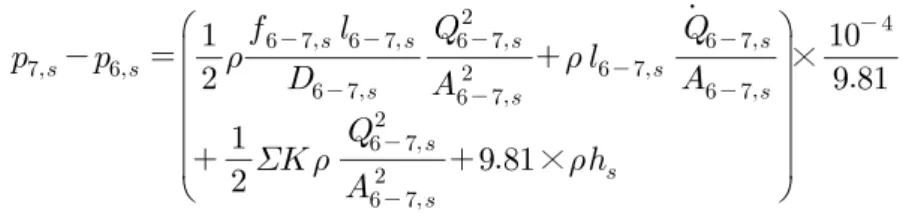
4.2.3. Pressure analysis in clap pump
As discussed in a previous chapter, the volume variations between two adjacent rotor jaws caused by hypo-cycle mechanism produces the flow in the pump as shown in fig.4.2. In order to apply equation (4.5) to the flow in this pump, all of the suction and discharge spaces in the pump were simplified to circular pipes as shown in fig.4.3. As a result, each of the suction and discharge spaces is divided into five independent control volumes. In other words, in case of suction, the space between two adjacent rotor jaws, inner suction port, suction chamber, outer suction port and suction pipe are independent control volumes respectively. In addition, the start points of each control volume are named as k,s (k : number of control
volume). The spaces of the discharge area are also divided in this manner, and
those start points are named as k,d. The space between the two adjacent rotor jaws, and inner suction and discharge ports, are adjusted based on the number of jaws. However, each space is merged with one of the control volumes. Therefore, the pressure losses in this pump can be expressed as:
× × (4.6)
× × (4.7)where, = number of control volume
= suction
= discharge