1. INTRODUCTION
An efficient and intelligent robot system design requires various technologies to liberate human from dangerous and difficult works. Human vision and tactics have been imitated for an intelligent robot, not completed yet, expanding those applications to a robot system. A robot with powerful data processing and storage owing to a computer is superior to human, being a powerful tool or equipment for substituting human works. A robot vision closely resembles human as far as technology progresses. Also, networking technology gives rise to tremendous change to human life, and it has been applied to a robot system by delivering a lot of commands and image data to a remotely placed robot in almost real time. In the light of an intelligent and efficient robot design, a virtual machine concept is applied to a robot system or manufacturing system, which is simulating a real system for enhancing the system performance [1, 5, 11]. A teleoperation, which is another effort to generate an efficient robot system, is accomplished by employing a networking [4,6,13].
In this article, we present an integrated system, which remotely controls and monitors a real robot by introducing a virtual robot design, and a network communication program. A tracking control for a 2D moving target integrated with the above schemes is given an example to evaluate the system performance. The system, as stated again, encompasses a camera vision, a tracking algorithm based on the camera information, and a network communication delivering command data and real camera image. The virtual robot design adopted from the kinematics solutions is addressed which excludes a direct signal feedback from the real robot, enabling to prevent undesirable operations due to the image and data communication error in a remote operation, and the way of synchronization with the real robot is developed.
The robot taken into consideration here is a serially articulated 5 dof type, and a vision camera is attached to the fifth link called a wrist. In this manner, a wider workspace can be guaranteed compared to a fixed camera system installed outside of the robot. A classical robot kinematics such as forward and inverse kinematics is employed to reach the target position which is identified by a camera image analysis.
A virtual robot is mainly designed to resemble the motion of the real robot, which can contribute to preventing blockage ahead or hassle, and an undesirable path moving. All directional views can be examined by an operator’s choice just
by dragging a mouse in the computer monitor, hence no longer relying on direct images coming from the cameras installed around the robot. All motions of the virtual robot are computed based on the robot kinematics, thus there might not be errors or malfunctions unless an operator handles improperly. The acquired image from the camera, which is caught by the wrist camera, is transferred to a PC to calculate the target position and velocity. The target tracking and grapping motions are also displayed on the virtual robot along with a real robot. The virtual robot is implemented by using an OpenGL tool in Visual C++ software [12].
Networking technologies are employed to accomplish a remote operation, where the robot position and orientation are monitored through a remote window, so called a client computer. At the same time, a server program is provided to control the real robot. The monitoring and control programs on both server and client provide an easy operation whether an operator is located at remote place or at real robot. Since the camera image data possess a big size memory, appropriate data compression for network communication is needed, which enables to demonstrate movie images in almost real time. At the same time, the virtual robot generated at the server program also appears to the client program through a network.
The article consists of robot system configuration, virtual robot development and its control method, target image analysis by robot vision, remote control, and monitoring based on networking. All subjects are systematically integrated in order to carry out a remote real time control and monitoring operation.
2. System configuration
A 5 dof articulate robot is employed to develop a remote control and monitoring system associated with 2D tracking control by a robot vision, virtual robot representation, and data communication in a networking. The robot is controlled by MMC (Multi Motion Controller) [10], where a library program is provided for a program development. A target is on the plate moving along x-y axes, which is controlled by two motor drivers. A camera is attached on the wrist, the fifth link, and it acquires instant image and transfers it to an image grabber connected to a PC. The 2D moving target the robot takes commands from the controller after the target is identified through a camera vision processing. At the same time, the robot motion associated with the tracking is
Remote Monitoring and Control of the Real Robot associated with a Virtual Robot
Byung Joon Jeon
*, and
Dong Hwan Kim
***Department of Mechanical Design Seoul National University of Technology, Korea
**
School of Mechanical Design and Automation Engineering, Seoul National University of Technology 172 Gongneung-dong, Nowon-gu, Seoul, 139-743, Korea(Tel : +82-2-970-6362; E-mail: [email protected])
Abstract: A robot system encompassing a remote control and monitoring through a virtual robot design is addressed and a tracking problem for a 2D (2 dimension) moving target by a robot vision is chosen as a case study. The virtual robot is developed, and it synchronizes with the real robot by compensating delay time. Two systems are displayed on a remote panel by communicating command and image data. The virtual robot utilizes an OpenGL library in Visual C++ environment. Additionally, the remote monitoring and control between the real robot and the virtual robot are accomplished by employing an appropriate data compression in a network communication
.
represented in the form of the virtual robot programmed by an OpenGL library in Visual C++. Finally, all motions are displayed both at the remote computer (as a client) and at the server computer through a networking communication.
3. VIRTUAL ROBOT DESIGN
3.1 Virtual robot structureIn this article, we construct a virtual robot displaced on a computer monitor by utilizing an OpenGL software based on Visual C++.
Fig. 1Virtual robot design flow in OpenGL
By combining the OpenGL structure and the information of the robot kinematics, a virtual robot design is developed and its design procedures are shown in Fig. 1. The first step for building the virtual robot is to make it possess the same mechanism and kinematics with the real robot, and all geometric information on the real robot are stored in the form of “Vertex data” [12]. The vertex data from the real robot are transformed to generate another data to be fit on the computer monitor, matching with the rendered data through OpenGL. Finally every frame data for the virtual robot goes into the frame buffer, eventually appearing on the PC monitor.
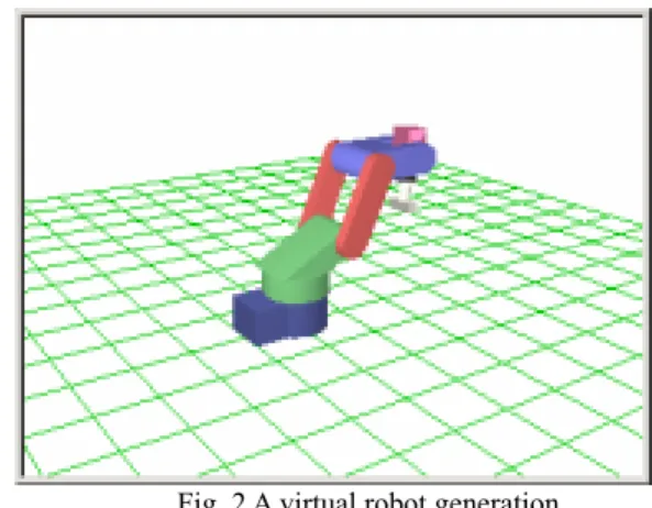
The virtual robot accompanying the above procedures is represented in Fig. 2. The kinematics of the real robot is surely employed to provide the virtual robot with correct data set. The frame speed is determined from the angular velocities of the 5 joints, which are coming from the operator’s predefined setup, not from direct angular velocities feedback. Usually, the operator just assigns average angular velocity for each joint to determine the frame speed. However, in a real robot operation, the robot takes appropriate acceleration/deceleration values in the starting and ending operations, which prevent an undesirable jerk and guarantee a smooth movement. In the sequel, there is an inevitable discrepancy between the real robot and the virtual robot as taking only average joint velocity. Therefore, synchronization between two robots is of importance, which indicates that two robots move identically at every step. Slightly different or wrong information gives rise to an unsatisfactory movement in the virtual robot. The frame generation speed for the virtual robot needs to be adjusted considering the acceleration/deceleration of the real
robot, which is a crucial issue for a perfect synchronization between two robots, and the detail is explained in the later section.
Fig. 2 A virtual robot generation 3.2 Virtual robot implementation
The robot kinematics of the 5-dof robot is utilized to build the virtual robot, distinguishing other virtual robot design that takes feedback signals from the real robot by using a touching device or a cyber glove, called a direct reflective robot [1,5,11]. This kind of virtual robot has a disadvantage with regard to the undesirable operation such as an obstacle collision or a malfunction associated with data communication error. In other words, when the real robot moves more out of range or to an unspecified location, the virtual robot does not catch or predict the coming troubles since it just follows the positions and velocities of the real robot, hence an undesirable operation may not be avoided adequately in advance. Furthermore, a data communication error or misleading data set gives rise to a serious operation to the remote robot due to simple reliance on the feedback signals. To tackle this hassle, the virtual robot taking kinematics information from the real robot along with forward and the inverse kinematics is proposed here and it shows more reliable operation at the real robot than the virtual robot by direct feedback.
3.3 Synchronization between real robot and virtual robot
When the target position and the orientation for gripping are determined, which are expressed by the end-effector coordinate, the associated set of joint angles for each joint is computed based on the inverse. In computing velocities for the 5 axes to synchronize the real robot and virtual robot, average velocities which divide the distance to the target by the desired time to reach the target is used in an initial try. In a real robot operation, however, some amounts of acceleration and deceleration are imposed on the robot motion control to make a smooth start and stop. On the other hand, the virtual robot only takes constant increment per every step, simply from the average velocity. From the point of view that the virtual robot should follow the real robot; the close arrival to the final destination and synchronized motion at every motion frame may not be accomplished by simple average velocity set for each joint, yielding a discrepancy between two robots. Therefore, the acceleration and deceleration actually need to be taken into consideration in generating the virtual robot in order to synchronize two robots. In Fig.3, the acceleration/deceleration compensation is illustrated, which makes the areas of two velocity patterns (as denoted as real and virtual robot velocity patterns in
Call OpenGL functions Transform and lightening Rasterization Frame buffer PC monitor Inverse kinematics Virtual robot position
Fig. 3) be identical by decreasing the initial constant averaged velocity of the virtual robot. Ultimately, this scheme, even if it looks simple, results in diminishing discrepancy between two robots, and whole experimental data based on this scheme is shown in later section. ta and t in Fig.3 represent the end time of acceleration d range and the starting time of deceleration range, respectively.
Fig.3 Acceleration/deceleration compensation for a virtual robot
With compensating the acceleration/deceleration, the virtual robot can reach the target at the same time as the real robot does even if the intermediate motions between two robots do not exactly match, but averagely being synchronized.
Fig. 4 Procedures of displaying position of the virtual robot
The procedures for the virtual robot representation are summarized in Fig. 4. Let θ∆ ,
θ
T, andθ
N be the joint movement, joint target, and current joint angle, respectively. T, andt
sare the approaching time to the target, and the sampling time. For every sampling time, the virtual robot moves by the amount of θ , joint velocity I increment, through which the virtual robot motion is displayed to be synchronized with the real robot if the deficiency is decreased sufficiently.3.3 Target tracking algorithm
The coordinates for camera image (x and y axes) and robot are usually set by different coordinates. To identify the target, a coordinate transform between two coordinates is needed. Basically, the camera coordinate is differently scaled with the robot coordinate and y-axes are reversed each other. When the robot receives the command for target gripping, it moves fast to the position where the camera starts taking a shot. From then, z direction of the end-effector is fixed, only x and y axis movements of the robot are involved to take shots. The camera utilized in this experimental setup has 320x240 pixels and the working space of the robot (target space) corresponds to 240mm width (x axis) and 170mm height (y axis). Therefore, one pixel along x-axis is 240/320=0.75 mm/pixel, and along y-axis is 170/240=0.70833 mm/pixel, respectively.
For a 2D tracking, a target location needs to be estimated first where it will reach at specified time. When this location is estimated, the robot gripper should reach the expected target location in advance before the target arrives, and stands by until the target passes the gripping location determined from the estimation. Finally, the gripper grips the approaching target instantly by lowering down the robot and closing the gripper.
Suppose the target travels along x and y axes with constant velocities within a workspace, not necessarily equal, i.e., x and y axis velocities can be set differently by moving a x-y table with different velocities. The velocity of the moving target is calculated based on two points identified from the camera shots with appropriate time interval. Later, the target is assumed to keep this velocity until captured at the specified location.
Now the locations of the two image shots are designated by Q1(x1,y1), Q2(x2,y2), and the gripping
location by ( , ) 3 3 3 x y
Q as illustrated in Fig. 10.
Fig. 5 Locations of moving target for camera image shots
Also, the distance between Q1 and Q2 is assigned as l1 , and between Q2 and Q is by 3 l2 .
Then l1is easily calculated as 2 1 2 2 1 2 1 (x x) (y y) l = − + − (1) a
t
t
d velocity
time Virtual
robot velocity Real robot velocity patternInitial constant velocity
Determine the target and arriving time for end-effector
Solve inverse kinematics
Joint movement: ∆
θ
=θ
T−θ
NJoint velocity: θV =∆θ/T Joint velocity increment θI =θV/ts
Virtual robot displays by adding θI for every sample
until ∆θ =0 l2 l1 First shot Q1 (x1,y1) Second shot Q2 (x2,y2) Grapping location Q3 (x3,y3)
τ
x
y
The target velocity
v
is computed when the camera shot time between Q1and Q2 is given as t11 2 1 2 2 1 2 1 1 ( ) ( ) t y y x x t l v= = − + − (2) Because the target velocity is assumed constant, the gripping location ( )
3 3 3x,y
Q can be computed when the
gripping time is given t2 after the second shot as follows ) )( 1 ( ) cos( ) ( ) cos( ) ( 1 2 1 2 2 1 2 1 3 x x t t t v l l l x − + = + = + = τ τ (3) ) )( 1 ( ) sin( ) ( ) sin( ) ( 1 2 1 2 2 1 2 1 3 y y t t t v l l l y − + = + = + = τ τ (4)
Of course, the assumption that the target velocity keeps constant does not seem to be realistic in general target tracking problem, but in a limited 2D operation such as a conveyor or a logistic system the moving target or object can be constrained with a constant velocity. For gripping a moving target, there are several algorithms. A generally known algorithm is to follow the target directly by continuously taking camera shots and identifying where it moves, and the other way is to increase the number of shots to get more precise location and velocity changes. However, to catch exact location of the target as it moves, these ways require complicated camera image identification schemes and minimum processing time to align the identified location by image processing with the real target location. To rely on these schemes ultimately requires highly costly equipments and large computational load. On the other hand, in this article, an integrated system development for a remote control and monitoring along with a virtual robot and network communication is a primary issue, hence a relatively simple algorithm of gripping the moving target is adopted to verify the performance of the integrated system.
4. NETWORK COMMUNICATION
When a remote operation and monitoring is considered, the command from a remote operator needs to be executed in real time, and the camera image for monitoring a target should be transferred to the operator without a serious time delay. At the same time, the motion of the designed virtual robot should match with the real robot as exactly as possible, eventually delivering it such that an operator recognizes in an almost real time base. To communicate between the operator and the robot, all information is transferred through a network, which prevails in a communication world. In this article, WinSock API (Windows Socket Application Programming Interface) is adapted to transfer data and image between on-site PC (real robot location) and remote PC (operator side) through a network. Two protocols exist at a transport layer served in the API, namely TCP and UDP, which possess a stream type socket and a datagram type socket, respectively [9]. The stream type socket is a connection-oriented socket that two process sockets are surely open before communication starts. On the other hand, the datagram
type socket is a connectionless socket that does not require socket opening before communication, hence it guarantees fast data transfer even if there could be a possibility of imprecise data delivery. In this article, the latter socket is employed to ensure a fast data transfer for image data even if there might be a slight image distortion as long as the image remains within a discernible range. On the other hand, the command data not requiring large sized data, crucial for a precise operation, can be exactly delivered by this protocol. For a visualized operation, a sever and a client program are developed, which both encompass robot vision, virtual robot via OpenGL, and network.
4.1 Server and client programs
A server program consists of a robot vision, virtual robot, and network program, which dedicates to monitoring and controlling the real robot directly. At the left figure of Fig.6, a camera monitor is displayed on the left top menu, and a virtual robot is on the right top. The robot control buttons are shown on the middle, and robot axes data are displayed on the bottom.
4.2. Client program
Fig. 6 A server program (left) and a client program (right) through network based control and monitoring
A client program displays information coming from a server through a network, and also controls the server program. The camera image data are transferred to the server first, and later delivers to the client after feasible data compression by JPEG format [8], accomplishing a real time monitoring. The structure of the client program is similar to the server program in respect of encompassing real camera image, virtual robot, robot control commands, and axes angles information. On the right side of the Fig.6, the developed server program is illustrated. Here, it is proven that the camera image, virtual robot, and axes data are all transferred via a network without significant time delay or data distortion.
5. EXPERIMENAL RESULTS
5.1 Synchronization between real robot and virtual robot
In order to estimate the arrival time for the end-effector to reach to the target position, repetitive experiments are done. The time is dependent on where the target locates, and it is approximately within 2 sec for a current experiment setup, indicating the target needs to be gripped in this time range. As the target velocity increases, the arrival time decreases. Therefore the robot should move fast to track the target. Nevertheless, the target should not escape from the range of the camera image frame. It is indicative that the camera shots to estimate a location of the target for gripping should be done before the target image disappears from the image frame. At the same time, during the robot tracking for the 2D moving target gripping, the virtual robot motion should follow the real robot, which can be done by updating new frame with
appropriate increment rate, eventually synchronizing with the real robot.
Two cases for a virtual robot movement to see how they synchronize are done: without acceleration/deceleration compensation and with compensation. First, when the acceleration/deceleration is not compensated, just taking the average joint velocity, there is some amount of deficiency between the real robot and the virtual robot as shown in Fig. 7.
(c) deficiency 0 2000 4000 6000 8000 10000 12000 14000 16000 18000 20000 1 4 7 10 13 16 19 22 25 28 31 34 Numbers of Sampling Pu ls e Axis 0 Axis 1 Axis 2 Axis 3 Axis 4
Fig. 7 Deficiency of joint angles between real robot and virtual robot two robots (without accel/decel compensation)
Considering the encoder output used in this experiment, where 1 degree corresponds to 2275 pulses, it implies that the error between two robots is not much serious even if the compensation is not made. Now, to obtain more accurate synchronizing between two robots, the acceleration/deceleration compensation is adopted as stated in the previous section, showing less error for every joint as plotted as in Fig.7. These results are done for three locations (far, medium, and near from the reference frame: denoted by 1,2,3 in horizontal axis), ensuring that the errors are remarkably diminished compared with the non-compensated case. deficiencies 0 1000 2000 3000 4000 5000 6000 7000 8000 1 2 3 4 locations pu ls e 0 Axis 1 Axis 2 Axis 3 Axis 4 Axis
Fig. 8 Deficiencies of two robots for different target locations (with accel/decel compensation)
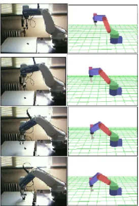
As the target location is far from the starting position, the moving velocity of the robot increases to reach there within specified time, causing larger deficiency than the near target location. But we do not change the velocity of the virtual robot for the far location tracking especially, just making acceleration/deceleration compensation by adjusting the average velocity. By virtue of this, the deficiency for every location becomes much smaller than the non-compensated case. This provides almost perfect synchronization between two robots. Fig. 8 illustrates the demonstration how two robots are synchronizing. However, even after the compensation, we see still quite small synchronizing error. This is mostly from the mechanical delay at start and stop
stages due to the substantial amount of frictions at each joint, which can be somehow inevitable.
Fig. 8 Demonstration for synchronization of two robots: (a) Real robot (b) Virtual Robot
6. CONCLUSIONS
We have presented several outcomes regarding to the remote robot monitoring and control that encompasses a virtual robot design and its synchronization with the real robot, 2-D moving target tracking through a camera image processing, and network communication between client and server. All subjects are integrated systematically to implement a real time control and monitoring of a robot. Acceleration/deceleration compensation is introduced to accomplish the precise synchronization between two robots. With the help of the virtual robot, which utilizes robot kinematics, undesirable operations are predicted in advance compared with the system relying on the direct feedback of sensor signals. System performance for a remote operation is verified by showing an example of 2D tracking problem associated with many functions such as camera vision, virtual robot design, and remote data communication on network. All functions are mutually screened whether they are reciprocally connected to surmount obstacles in terms of data delay or undesirable operation due to miscommunication.
6.3 References
[1] C. Basdogan, C.-H. Ho, M. A. Srinivasan, and M. Slater, An experimental study on the role of touch in shared virtual environments, ACM Transactions on Computer-Human Interaction, Vol. 7 No. 4, pp. 443~460, 2000
the CyberGlove as a whole-hand input device, ACM Transactions on Computer-Human Interaction (TOCHI), Vol. 2, No. 4, pp. 263~283, 1995
[3] K. Schäfer, B. Brauer, and W. Bruns, A new approach to human-computer interaction—synchronous modelling in real and virtual spaces, Proceedings of the conference on Designing interactive systems: processes, practices, methods, and techniques, pp. 335 – 344, 1997
[4] G.. Dodds, T. Ogasawara, N. Glover, and K. Kitagaki, Telerobot control and real-time simulation environment using parallel processing, Control Theory and Applications, IEE Proceedings, Vol. 143, No. 6 , pp.543 ~550, November 1996
[5] F. Lamiraux, S. Sekhavat, and J.-P. Laumond, Motion planning and control for Hilare pulling a trailer, IEEE Transactions on Robotics and Automation, Vol. 15, No. 4, pp. 640 ~ 652, 1999
[6] X.-G.. Wang, M. Moallem, and R.V. Patel, An Internet-based distributed multiple-telerobot system, IEEE Transactions on Systems, Man and Cybernetics, Vol. 33, No. 5, pp. 627 ~634, 2003
[7] M. Sweet, OpenGL Super Bible, 2nd Ed., 2001.
[8] Samsung Electronics, MMC user’s manual, 2002. [9] Matrox, Matrox Imaging Library v6.0, user manual, 1999. [10] J.J. Craig Introduction to Robotics: Mechanics and Control“, 2nd Ed., Addison Wesley Longman Inc, 1998.
[11] E. R Davies, Machine Vision: Theory, Algorithms, Practicalities, 2nd Ed., Academic Press, 1996.
[12] E. Trucco, Introductory Techniques for 3-D Computer Vision, Prentice Hall, 1998.
[13] D. Roberts, Developing for the Internet with WinSock, 1998.