15-3 / J. Lee
• IMID 009 DIGEST
Abstract
We developed highly efficient blue PHOLEDs with reduced roll-off by using a mixed host structure. The balanced charge carrier injection and the distributed recombination zone within emissive layer resulted in a highly stable efficiency roll-off with quantum efficiencies of 20.1 and 18.1 % at a luminance of 1000 and 10000 cd/m2.
1. Introduction
Organic light-emitting devices (OLEDs) have been received considerable attention for both display and lighting applications due to their high light-emitting performances.1-5 Especially, electro-phosphorescent
organic light-emitting diodes (PHOLEDs) using green and red phosphorescent dyes have reached almost 100 % internal quantum efficiency by efficient utilizing both singlet and triplet excitons.2 However,
there are still several challenges for highly efficient blue PHOLEDs because they require wider band-gap materials for both host and dopant than those for green or red PHOLEDs. There have been many studies to improve the performance of blue PHOLEDs through the development of device structures such as adequate interlayer, stepwise doping or double emissive layer structure.3 Even though these
encouraging reports, there is still room for further improvement in the efficiency of the blue PHOLEDs, especially at a high current density region.
The efficiency of PHOLEDs tend to decrease at a high current density region (i.e. efficiency roll-off) due
to triplet-triplet annihilation (TTA) or triplet-polaron annihilation (TPA) in the emissive layer (EML).3-4
One effective approach to reduce the efficiency roll-off is to use a mixed host system instead of using a
single host material.5,6 Recently, we have reported
efficient blue and white PHOLEDs with a mixed host system by using a ultra wide band gap host of m-bis-(triphenylsilyl)benzene (UGH3).6
In this work, various mixed host structure of blue PHOLEDs were developed to study the relationship between the device performances and the combination of host materials. As a mixed host layer, a hole transport-type host material, (H-Host), was combined with an electron transport-type host material, (E-Host) or a bipolar transport-type host material, (B-Host). Additionally, device characteristics, particularly to study recombination zone distribution, were also investigated according to orange light-emitting sensing layer inside the EML. We found that a mixed host structure was effective to control the charge carrier injection and exciton distribution in emissive layer (EML), thus obtained highly improved and stable efficiency in blue PHOLEDs.
2. Experimental
A series of blue PHOLEDs in this study were fabricated using the configuration: indium tin oxide (ITO) (70 nm)/1,1-bis[(di-4-tolylamino)phenyl] cyclohexane (TAPC) (50 nm)/EML (30 nm)/1,3,5-tri(m-pyrid-3-yl-phenyl)benzene (Tm3PyPB) (20 nm)/Tm3PyPB:Cs (30 nm)/LiF (1 nm)/Al (120 nm). Two different mixed host devices were prepared to investigate the effect of host material properties on device characteristics. Two standard devices with single B-Host or E-Host were also fabricated as references for comparison.
Bipolar type B-Host or electron transport-type E-Host composition in the mixed host device was 50 %. A blue light emitting iridium(III)bis(4,6-difluorophenyl)-pyridinato-N,C2’) picolinate (FIrpic)
was doped in mixed host emissive layer and the doping concentration of FIrpic was fixed at 10%. To achieve the efficient blue PHOLEDs, effective confinements of both charge carriers and triplet excitons are necessary. Therefore, TAPC and Tm3PyPB with wider triplet energy level (T1= 2.9 and
Stable efficiency roll-off in blue phosphorescent organic
light-emitting diodes using a mixed host structure
Jonghee Lee1, Jeong-Ik Lee1, Jun Yeob Lee2, and Hye Yong Chu1,* 1Convergence Components & Materials Research Laboratory, Electronics and
Telecommunications Research Institute, Daejeon, 305-350, Republic of Korea
Tel.:82-42-860-6876, E-mail: [email protected]
2Department of Polymer Science and Engineering, Dankook University, Yongin-si 448-701, Republic of Korea
15-3 / J. Lee
IMID 2009 DIGEST •
2.78 eV, respectively, which are higher than that of FIrpic (T1 =2.62 eV)) and low-lying the highest
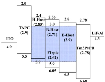
occupied molecular orbital (HOMO) and high-lying the lowest unoccupied molecular orbital (LUMO) energy levels, respectively, were used as a hole-transporting layer (HTL) and as an electron transporting layer (ETL), respectively. The energy level diagrams of materials used in this study were shown in Fig. 1.
ITO was cleaned by the standard oxygen plasma treatment. The OLED grade materials were purchased and used without further purification. All organic layers were deposited in a high vacuum chamber below 5 x 10⁻⁷ torr and thin films of LiF and Al were
deposited as a cathode electrode. The OLEDs were transferred directly from vacuum into an inert environment glove-box, where they were encapsulated using a UV-curable epoxy, and a glass cap with a moisture getter. The electroluminescence spectrum was measured using a Minolta CS-1000. The current-voltage (I-V) and luminescence-voltage (L-V)
characteristics were measured with a current/voltage source/measure unit (Keithley 238) and a Minolta CS-100.
Fig. 1. Energy level diagram materials used in this study.
3. Results and discussion
In this mixed host devices, we found that the charge carrier density and injection properties in the EML were correlated with combination of the host materials, and could be controlled by host layer engineering.
The current density-voltage-luminance curves of
the Device A Host:B-Host) and Device B (H-Host:E-Host) are shown in Fig. 2 The current density of both Device A and B were dramatically increased with the introduction of H-Host in the mixed host devices. Since FIrpic is a well-known electron transport-type triplet emitter and their relatively low-lying LUMO level compared with those of B-Host and E-Host, the electrons injection and transport behavior of both Device A and B would be similar. Therefore, the increased current density with the addition of H-Host is mainly originated from facilitated hole injection and transport from TAPC to B-Host (or E-Host) through the H-Host. As shown in Fig 1, the hole injection from TAPC to B-Host was slightly restricted due to the HOMO level difference of 0.55 eV between TAPC and B-Host. However, in the case of Device A (H-Host:B-Host), the hole injection from TAPC to EML was enhanced by H-Host addition which has higher-lying HOMO level (5.7 eV) than that of B-Host (6.05 eV). In addition, the hole mobility of H-Host is higher than that of B-Host. Therefore, increased current density in the Device A (H-Host:B-Host) could be obtained. The luminance at the same voltage was also increased as similar as the current density behavior.
In the case of the combination of H-Host and an electron transport-type E-Host (Device B), the current density behavior was more dramatic than that in the case of Device A. This is attributed to the huge hole injection barrier (1.0 eV) from TAPC to E-Host as well as the inferior hole mobility of E-Host compared to that of B-Host. In addition, the driving voltages of mixed host devices were much lower than those of single host devices.
0 1 2 3 4 5 6 7 8 9 10 11 0.0 0.1 0.2 0.3 0.4 0.5 Voltage (V) Cu rre nt de ns ity (A /cm 2) 0.1 1 10 100 1000 10000 100000 H-Host:B-Host B-Host H-Host:E-Host E-Host Lum ina nce (cd /m 2 )
Fig. 2. Current density versus voltage (I-V) and
voltage versus luminance (V-L) characteristics of
blue PHOLEDs in this study.
ITO 4.9 TAPC (2.9) 2.0 5.5 LiF/Al 4.3 6.68 Tm3PyPB (2.78) 3.0 5.9 2.8 6.5 E-Host (2.9) H-Host (2.85) 6.05 2.56 B-Host (2.71) 5.7 2.4 2.78 FIrpic (2.62)
15-3 / J. Lee
• IMID 009 DIGEST
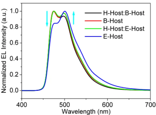
Figure 3 shows the electroluminescence (EL) spectra of the blue PHOLEDs in this study at a current density of 10 mA/cm2. All blue PHOLEDs exhibited a
similar maximum luminescence wavelength, near 474 nm, which is originated from the triplet emission of FIrpic emitter. However, as the H-Host introduced in the EML, the shoulder emission around 500 nm was decreased in both Device A and B.
We found that these spectral changes were related with optical effect through the recombination zone shift. To carry out recombination zone study of the mixed host devices, blue PHOLEDs with an orange light-emitting sensing layer were prepared by using bis(2-phenylbenxothiozolato-N,C2’)iridium (III)
acetylacetonate (Bt2Ir(acac)). In the case of E-Host
only device, the hole and electron recombination is positioned in the HTL/EML interface due to preferred charge (electron) carrier mobility of E-Host material. However, the recombination zone of the Device B with H-Host:E-Host mixed host structure would be shifted from the HTL/EML side to the center of the EML as introducing H-Host content in the EML. In other words, balanced exciton recombination in the EML could be achieved by using a mixed host structure, in which enhancement of light-emitting efficiency was expected. The detailed investigations about the recombination zone shift will be discussed in the presentation. 400 500 600 700 0.0 0.2 0.4 0.6 0.8 1.0 H-Host:B-Host B-Host H-Host:E-Host E-Host Wavelength (nm) No rm ali ze d E L I nte ns ity (a .u. )
Fig. 3. Normalized electroluminescence (EL) spectra of blue PHOLEDs in this study.
The external quantum efficiency (EQE) of the blue PHOLEDs with mixed host structure were plotted against (a) luminance or (b) current density in Fig 4. Both Device A and B with mixed host structure
showed improved performance than B-Host or E-Host only devices. The efficiency improvement was not considerable in the case of B-Host only device and Device A (H-Host:B-Host) due to charge carrier balance of B-Host material. However, Device B (H-Host:E-Host) showed distinguished efficiency enhancement with a peak EQE of 20.1 %, which is over three times higher than 6.6 % in single E-Host device at a luminance of 1000 cd/m2. 1 10 100 1000 10000 100000 0 2 4 6 8 10 12 14 16 18 20 22 (a) H-Host:B-Host B-Host H-Host:E-Host E-Host Ex ter na l Q ua ntu m Ef fic ien cy (% ) Luminance (cd/m2)
1E-5 1E-4 1E-3 0.01 0.1
0 2 4 6 8 10 12 14 16 18 20 22 (b) H-Host:B-Host B-Host H-Host:E-Host E-Host Ex ter na l Q ua ntu m Ef fic ien cy (% )
current density (A/cm2)
Fig. 4. External quantum efficiency versus (a) luminance and (b) current density characteristics of blue PHOLEDs in this study.
Another remarkable attention is that roll-off of
mixed host devices were less severe than that of single host device. The EQEs of the Device A (H-Host:B-Host) and Device B (H-Host:E-(H-Host:B-Host) showed over 18 % at a luminance of 10000 cd/m2 and decreased to
half at a current density of J0= 382 and 230 mA/cm2,
15-3 / J. Lee
IMID 2009 DIGEST •
efficiency roll-off values for blue electro-phosphorescent devices, indicating a highly reduced
roll-off in efficiency.
These enhanced EQE in the mixed host devices is mainly due to charge carrier injection/transport balance as well as recombination region distribution within EML by the optimization of mixed host properties. Moreover, this behavior was more dramatic in Device B because E-Host material is an electron transport-type material while B-Host is a bipolar material. The distributed recombination zone through balanced charge carrier injection/transport in the mixed host devices also showed remarkably stable efficiency roll-off.
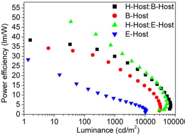
Additionally, high EQEs along with lower driving voltages in the mixed host devices resulted in improved peak power efficiencies compared to those of B-Host or E-Host only devices. The peak power efficiencies of Device A and B were reached up to 38.4 and 47.9 lm/W, respectively, as shown in Fig 5.
1 10 100 1000 10000 100000 0 5 10 15 20 25 30 35 40 45 50 55 H-Host:B-Host B-Host H-Host:E-Host E-Host Luminance (cd/m2) Po we r e ffic ien cy (lm /W )
Fig. 5. Power efficiency versus luminance characteristics of blue PHOLEDs in this study.
4. Summary
In summary, we have shown that the light-emitting performances of blue PHOLEDs could be enhanced by host layer engineering. Mixed host structure devices showed effective distribution of recombination zone as well as balanced charge carrier injection, which resulted in highly improved efficiency roll-off at high current density.
Acknowledgement
We gratefully acknowledged Ms. K. -I. Song and Ms. S. J. Lee (ETRI) for assistance with EL measurements. This work was supported by the future technology development program of MOCIE/ITEP [2006-10028439, OLED Lighting].
5. References
1. G. W. Scherer, J. Am. Ceram. Soc., 73[11], p.3
(1990).
1. M. A. Baldo, D. F. O’Brien, Y. You, Shoustikov, S. Sibley, M. E. Thompson, and S. R. Forrest, Nature,
395, p.151 (1998).
2. C. Adachi, M. A. Baldo, M. E. Thomposon, and S. R. Forrest, J. Appl. Phys. 90, p.5048 (2001).
3. S. -J. Su, T. Chiba, T. Takeda, and J. Kido, Adv. Mater.20, p.2125 (2008).
4. S. Reineke, K. Walzer, and Karl Leo, Phys. Rev. B.
75, p.125328 (2007).
5. M. E. Kondakova, T. D. Pawlik, R. H. Young, D. J. Giesen, D. Y. Kondakov, C. T. Brwon, J. C. Dealton, J. R. Lenhard, and K. P. Klubek, J. Appl. Phys.104, p.094501 (2008)
6. J. Lee, J. I. Lee, J. Y. Lee, and H. Y. Chu, Appl. Phys. Lett.94, p.193305 (2009)