ICCAS2005 June 2-5, KINTEX, Gyeonggi-Do, Korea
Design and Implementation of XCP Network System
Jong Man Heo∗, Hyoung Koo Kang∗, Woo Young Kim∗∗, Wook Hyun Kwon∗∗Control Information Systems Lab., School of Electrical Engr.
and Computer Science, Seoul National University, Seoul, 151-742, Korea (Tel: +82-2-873-2279; Fax: +82-2-878-8933; Email: [email protected])
∗∗Xeline Co., Ltd. 7F, Chungjin Bldg., 475-22 Bangbae 2-dong Seocho-gu, Seoul 137-819, Korea
(Tel: +82-2-598-0980; Fax: +82-2-598-0975; Email: [email protected])
Abstract: This paper describes the design and implementation of a XCP (Xeline Control Protocol) network system. XCP is an information oriented protocol which delivers information with high reliability according to the predefined rule. The XCP network system is implemented with partly hardware and partly software based on the power line communication(PLC) environment. A network management tool which interacts with devices is also developed. In order to verify the feasibility of the proposed architecture, the implemented XCP network system is evaluated using a lighting control system.
Keywords: Xeline Control Protocol (XCP), networked control system, power line communication, network management tool
1. Introduction
A networked control system (NCS) is defined as the system with one or more control loops closed via a serial communi-cation channel. NCS is an integration of sensors, actuators, controllers, and communication network [1],[2]. NCS has significantly more advantages, including lower cost, reduced power, simpler installation and maintenance, flexibility, and higher reliability than a non-networked based control sys-tem [3]. NCS is widely used in the manufacturing plants, HVAC (heating, ventilating and air conditioning) systems, aircraft, and many other contexts. To exchange informa-tion and control signals between control devices in this net-worked control system, several network protocols have been developed, including CAN (controller area network) for au-tomotive and industrial automation [4], BACNet (building automation and control networks) for building automation [5], LonWorks for different applications [6], and Fieldbus for process control [7].
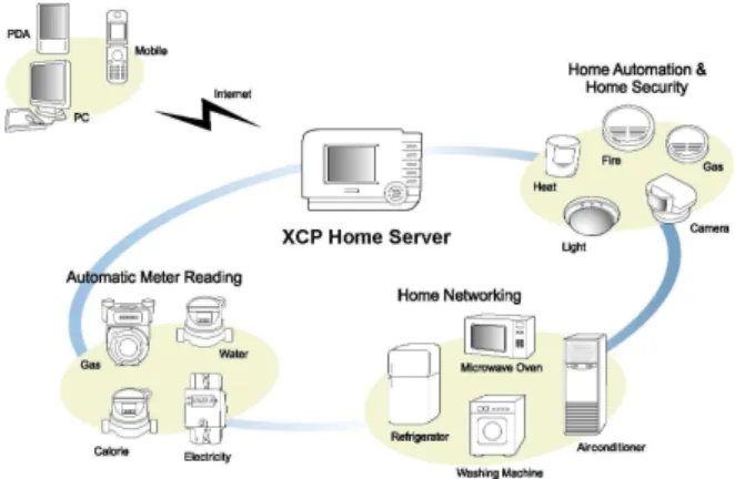
This paper proposes new control protocol, Xeline Control Protocol (XCP) for the networked control system [8]. The XCP protocol is a layered and packet based protocol, and has several advantages including communication stability, and flexibility. The proposed protocol is defined to operate on any of the acceptable media for twisted pair, IrDA, and wireless, as well as power line. The XCP protocol is an infor-mation oriented protocol which delivers inforinfor-mation from a device to other devices automatically with high reliability ac-cording to the predefined rule. The XCP protocol may have a wide range of applications such as home/building/factory automation, home networking (home appliances, security, safety, etc.), and automatic meter reading (AMR) as shown in Fig. 1. In this paper, in addition to introducing new con-trol protocol, we implement and evaluate the XCP network system using the proposed protocol to verify the feasibil-ity for implementations. The communication stabilfeasibil-ity and flexibility of the XCP protocol are confirmed through the evaluation of the lighting control system.
The outline of this paper is as follows. Section 2 provides an overview of the XCP protocol. In Section 3, the proposed
XCP network system is implemented. An evaluation of the implemented XCP network system is described in Section 4. Finally, the conclusions are given in Section 5.
Fig. 1. Schematic diagram of a XCP network system
2. An Overview of XCP
This section describes some of the most important aspects of the XCP protocol.
2.1. Network Architecture
Fig. 2 shows the network architecture of XCP network sys-tem. Node is a device or modem within that XCP protocol is implemented. Every node has a unique node address within a subnet. Subnet is a set of nodes that share the same subnet address and the same encryption key. Every node that be-longs to the same subnet can communicate with each other without a router. There may be up to 240 nodes within a subnet. Domain is a set of subnets connected by routers. Domain is the network unit of management and administra-tion. There may be up to 240 subnets, and 57,600 nodes in a domain. A group is a logical set of nodes that perform similar functions within a domain. Groups facilitate one-to-many communication and are intended to support functional addressing. Grouping is an efficient method to improve the use of network bandwidth for packets addressed to multiple
nodes. There may be up to 128 groups in a domain, and 64 members in a group.
Fig. 2. Domain structure example 2.2. Addressing
To support networks with few devices to tens of thousands of devices, the XCP protocol uses several types of addresses. Packets can be transmitted to single node, to any group of nodes, or to all nodes in the network. As a physical
ad-dress, every XCP node includes a unique 64-bit serial
num-ber, which is assigned at shipment from the factory. The manufactured unique node serial number is used for an ini-tial network setup and management. Subnet address and
node address are assigned to each node on the network, and
are used to identify the location of the network. A node included in the specific group is assigned a 8-bit group
ad-dress and a 8-bit group member ID. A network management
tool that maintains a database of the addresses for the XCP network assigns the subnet addresses, node addresses, group addresses and group member ID (see Section 3.2.). Node ac-cess methods according to the address types are as follows.
• Unicast: One-to-one communication. Destination
ad-dress is given by subnet adad-dress(8 bit) and node adad-dress(8 bit).
• Multicast: One-to-many communication. Destination
address is given by group address. It broadcasts simulta-neously to the maximum 64 members belonged to a single group. One node can belong to the maximum 15 distinct groups.
• Broadcast: Many-to-many communication. Domain
wide broadcasting is performed when destination subnet ad-dress is “0xFF”, subnet wide broadcasting when destination node address is “0xFF”.
2.3. Layered Protocol Architecture
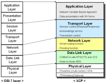
The XCP protocol conforms to the OSI (Open System In-terconnection, ISO 7498) model except for the session layer and the presentation layer as shown in Fig. 3. The XCP pro-tocol implements five layer: physical layer, data link layer, network layer, transport layer, and application layer. Each layer provides services for its upper layer and calls services provided by its lower layer using primitive.
Physical layer: The XCP protocol is media-independent, so several communication media such as power line, twisted
Fig. 3. XCP layer architecture
pair, IrDA, and wireless can be used in the XCP physical layer. Currently, only the specification of power line is de-fined. It uses multi-carrier modulation, and its data rate is up to 19kbps.
Data link layer: In data link layer, CSMA/CA (Carrier Sense Multiple Access/Collision Avoidance) with RTS/CTS (Ready To Send/Clear To Send) is used. The collision can be reduced by an addition of RTS/CTS function to the CSMA/CA method. Also, various QoS scheme is sup-ported through cannel access priority control. Node-to-node ARQ (automatic repeat request) and CRC (cyclic redun-dancy checking) are used to improve the communication re-liability. The communication between the nodes belonged to different subnets can be fundamentally blocked through an encryption. The communication security can be maintained from malicious hacking, and the encryption functionality is executed by 128 bit stream cipher.
Fig. 4. Frame format
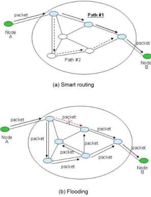
Network layer: XCP can select a routing method accord-ing to the channel condition. Because of noise, impedance mismatch, and signal attenuation, there exists a hidden node problem. For the hidden nodes within subnet inaccessible to a signal, the communication is tried by utilizing other nodes
as smart routers. Dynamic shortest path algorithm is used to search the shortest path without additional manual setup, and the path information is dynamically updated according to changing channel status. When the shortest path infor-mation to destination node is not available or the dynamic path is unstable, each node can converse routing method into the flooding mode. Flooding function guarantees higher suc-cess rate in the communication when smart routing is unable to assure the success of the communication. The drawback, however, is the increased communication traffic and long re-sponse time due to an adoption of random path method in-stead of shortest path method.
(a) Smart routing
(b) Flooding Fig. 5. Routing method
Transport layer: The XCP transport layer ensures reliable end-to-end delivery of packets. The transport layer handles loss and duplication of request and response packets. In particular, old duplicate request packets are discarded not to cause erroneous actions. Another function of the XCP trans-port layer is a transaction control service. Each packet has a 12-bit transaction ID, and the transaction ID and source address of the packet are used for the transaction control. Application layer: The XCP application layer promotes interoperability between control devices. In order for appli-cations from multiple vendors to easily interoperate, a net-work variable concept is adopted. Instead exchanging pack-ets with command set, the value of standardized network variable is exchanged so that different applications will ex-hibit common behavior for network variable updates. Fig. 4 shows the frame format of the XCP protocol. At the sender side, each layer’s protocol data unit (PDU) is en-capsulated descending the communication hierarchy within
a lower layer PDU when transmitted from one component to another. At the receiver side, an incoming data unit is processed in the reverse order up through the hierarchy. 2.4. Network Variable
The XCP protocol adopts the concept of network variable (NV) as similar to that of LonWorks protocol[6]. Network variable facilitates the design of information based control. An information present on the node is defined in forms of network variable. The network variable can be any data such as a switch value, light dimming, or timer value. An input network variable is that a specific node application is expecting to get from other nodes, and an output network variable is that one is expecting to make available to other nodes. Via a process which is called binding, the network variable is paired with the other network variable on remote node from output to input direction. As the current value of network variable is changed or meets the specific conditions, the information is automatically propagated to the binding network variables. The attributes of network variable can be updated dynamically. Users can freely add or delete the net-work variable in the node by programming. Fig. 6 shows the example of the network variable binding. In Fig.6, On/Off switch NV is output, and light NV is input network variable. At the binding process that takes place during network de-sign and installation, each network variable is paired, and parameters have been configured.
Fig. 6. Network variable binding example
3. Implementation of XCP Network System
The proposed protocol is implemented with partly hardware and partly software as shown in Fig. 7. The physical layer of the XCP protocol is implemented with hardware, and the upper layers of the XCP protocol are implemented with soft-ware.
3.1. Hardware Implementation of the XCP Protocol The XMDL-3000 PLC module is composed of a XPLC30 chip, which is Xeline’s proprietary low speed PLC MAC/PHY chip, some discrete components for analog front end and interface part. The XPLC30 chip consists of 32-bit ARM9 processor block, PLC communication block, and
Fig. 7. Layered architecture of XPLC30
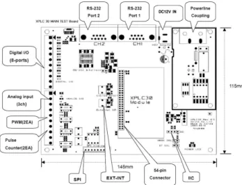
peripheral block inside it, so it can be fully operated as a stand-alone system without a additional micro controller unit (MCU). It uses multicarrier modulation scheme for PLC communication, and the bandwidth of less than 450kHz. A processor part of XMDL-3000 module performs the software function of MAC and upper layers for PLC interface and user application code. An analog front end part performs a function of analog filtering and automatic gain control, and an interface part performs a function of interface between XMDL-3000 module and main board. For an initial evalu-ation of XMDL-3000 module, it operates with XMDL-3000 main board. Fig. 8 shows an outline of XMDL-3000 main board, showing a board dimension and I/O ports. This main board includes the following elements: XMDL-3000 module, analog input, digital I/O, PWM (pulse width modulation), external interrupt, RS-232 port, and so on. The XMDL-3000 module and main board are assembled through 54-pin con-nector as shown in Fig. 9. The XMDL-3000 module can be embedded inside various appliances for home and building automation.
Fig. 8. XMDL-3000 main board dimension 3.2. Software Implementation of the XCP Protocol The MAC layer and upper layers are implemented on the XMDL-3000 module in firmware. The interaction between the MAC layer and other layers are described in terms of primitives where the primitives represent the logical ex-change of information and control between the MAC layer and other layers. The primitives between MAC layers and other layers are shown in Fig. 10. A M D DAT A req prim-itive is used to request that an upper layer payload be sent
Fig. 9. Implementation of the XMDL-3000 main board
and its parameters are the configurations such as the des-tination ID, the pointer and size of data packet which will be sent, the priority for access of power line, the transmis-sion type, and the encryption option. A M D DAT A conf primitive is used to indicate the successful transmission to the upper layer. A M D DAT A ind primitive indicates the arrival of upper layer PDUs received. P D DAT A primi-tives are provided by the physical layer to the MAC layer. A P D DAT A req primitive is used to request that a MAC PDU be sent. A P D DAT A ind primitive indicates to the MAC layer that the MAC PDU has been received from the physical layer. A P D DAT A conf primitive indicates to the MAC layer when the previously requested MAC PDU has been completely transmitted.
Medium
Fig. 10. Primitives
Network management tool, called XCP network builder, which interacts with nodes for the XCP network is also de-veloped as shown in Fig. 11. The XCP network builder provides a complete development environment which allows users to design, install, operate and maintain the XCP net-work system. With the XCP netnet-work builder, all tasks
asso-ciated with the administration of the XCP network can be handled: configuration of single node or entire networks and network diagnosis.
Fig. 11. XCP network builder
4. Evaluation of the Implemented XCP Network System
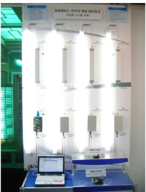
To evaluate the feasibility of XCP network system, we in-stalled and tested the networks which include the imple-mented node. Fig. 12 shows a lighting control system which consists a set of XCP nodes. Each node is composed of a flu-orescent lamp, a digital ballast module and a XMDL-3000 main board. In this demonstration setup, there exists four nodes in the network and the network is configured using XCP network builder. The digital ballast is controlled by PWM signal generated from XMDL-3000 board and it ad-justs lighting levels to the necessary value for each task.
5. Conclusion
The design and implementation of a new intelligent net-worked control system has been presented in this paper. The system is developed using the proposed XCP protocol. The XCP protocol features the following elements: layered and packet based protocol, information oriented protocol with network variable, transaction control service, smart routing and so on. We verified the feasibility of the implemented system through the experimental evaluation of the lighting control system based on power line environment. As a result, it is concluded that the XCP protocol provides the flexibility for the implementations.
References
[1] R. S. Raji, “Smart networks for control,” IEEE
Spec-trum, vol. 31, issue 6, Jun. 1994 pp. 49–55.
[2] G. C. Walsh, and H. Ye, “Scheduling of networked con-trol systems,” IEEE Concon-trol Systems Magazine , vol. 21, issue 1, pp. 57–65, Feb. 2001.
[3] D. Nesic, and A. R. Teel, “Input-output stability prop-erties of networked control systems,” IEEE
Transac-00
Fig. 12. Experimental testbed of a XCP network system
tions on Automatic Control , vol. 49, issue 10, pp. 1650–
1667, Oct. 2004.
[4] Road Vehicles-Interchange of Digital Information-Controller Area Network for High-Speed Communica-tion, ISO 11898, 1994.
[5] H. M. Newman, “Integrating building automation and control products using the BACnet protocol,” ASHRAE J., vol. 38, no. 11, pp. 36–42, Nov. 1996.
[6] Echelon Co., “LonTalk Protocol Specification Version 3.0” 1994.
[7] M. Santori, “A tale of three buses: DeviceNet, Profibus-DP, Foundation Fieldbus,” EDN, vol. 42, no. 22, pp. 149–160, Oct. 1997.