flange terminal bearing(inside) fixing roller flange terminal bearing(outside) bearing(inside) coil bobbin bearing(ouside)
Fig.1 Sectional view of toner fixing roller in copy/printer equipment
1. INTRODUCTION
In recent years, much promising interest to global environmental-friendly technology developments has grown up greatly and energy saving power utilizations relating to the office information automation (OA) and telecommunication equipment have become more and more significant.
The fixing heat roller processing schemes of a toner in a copy machine, facsimile and scanner are actually required for transferring toner on printing paper from a rolling drum with a certain pressure for a copying machine as well as a high-speed laser printer. At present, the cost effective toner fixing process equipments using the radiant heat energy by the sheathed heater or the halogen lamp heater have been applied for modern office information, telecommunication, facsimile, scanner and automation applications. In practice, this heat
energy utilization process part usually takes 90% of all energy needed for printing devices operation.
Therefore, the promising development of more effective energy-saving toner fixing process is a significant task of a large amount of great demand with a great advance of information technology. Such some electric heating methods being developed will lead to the improvement of the equipment in high speed and high efficiency. The direct heating of the fixing roller by induced eddy currents has attracted special interest recently as an alternative to the conventional light energy heating fixing roller by the halogen lamp, however; only a few numbers of publications and issues on this latest development subject have been sufficiently presented so far. In general, the non-contact eddy current-based induction heating of all types of the metals is safe, reliable, highly efficient, faster starting heating method that can allow controlling temperature more simply and
ZCS-PDM Series Resonant High Frequency Inverter for Copy Machine
Hisayuki Sugimura*, Ahmad Mohamad Eid*, Eiji Hiraki**, Sung-Jung Kim*,
Hyun-Woo Lee*, and Mutsuo Nakaoka*
* The Electric Energy Saving Research Center, Kyungnam University, Masan, Korea (Tel : +82-55-249-2625; E-mail: [email protected])
** Division of Electrical and Electronics Engineering, Yamaguchi University, Yamaguchi, Japan
Abstract: This paper presents the two lossless auxiliary inductors-assisted voltage source type half bridge (single ended push pull:
SEPP) series resonant high frequency inverter for induction heated fixing roller in copy and printing machines. The simple high-frequency inverter treated here can completely achieve stable zero current soft switching (ZCS) commutation for wide its output power regulation ranges and load variations under its constant high frequency pulse density modulation (PDM) scheme. Its transient and steady state operating principle is originally described and discussed for a constant high-frequency PDM control strategy under a stable ZCS operation commutation, together with its output effective power regulation characteristics-based on the high frequency PDM strategy. The experimental operating performances of this voltage source SEPP ZCS-PDM series resonant high frequency inverter using IGBTs are illustrated as compared with computer simulation results and experimental ones. Its power losses analysis and actual efficiency are evaluated and discussed on the basis of simulation and experimental results. The feasible effectiveness of this high frequency inverter appliance implemented here is proved from the practical point of view.
Keywords: Voltage source type series load resonant inverter, Half bridge inverter circuit topology, Lossless inductive snubbers,
Zero current soft switching, Pulse density modulation ratio control, Induction heated roller in copy machine, Consumer power electronics
High-frequency inverter
Cylindrical heating body (Fixing roller)
Working coil Resin bobbin
Fig.2 Induction heating fixing roller
M
L
2L
1R
2i
L1i
L2v
L1v
L2R
1≅
0
Fig.3 Transformer model of induction heating load
SW1
SW2
i
Q1D1
D2
Q1(SW1/D1)
Q2(SW2/D2)
v
Q1M
v
Q2i
Q2R
2L
2L
1v
LL
s2L
s1C
sv
csL
fE
dC
fi
LFig.4 Voltage source SEPP ZCS-PDM high frequency inverter system for inducrion heated fixing roller precisely. Therefore, this can lead to reducing the size of the
printing devices and their performances enhancement. Hence, new development of the high efficiency and high frequency
power supply for the induction-heating (IH) fixing roller in such epoch-making applications seems to be a very important and timely task from an energy saving point of view.
For industrial and consumer IH power applications in next generation, the voltage-fed high frequency inverter with series capacitor resonant tank circuitry is widely applied. The general method of output power regulation in this kind of high frequency inverter is pulse frequency modulation (PFM) of inverter frequency. The pulse frequency modulation scheme continuously implies changing the working frequency of the inverter that has essentially some drawbacks for non contact induction heating. The high frequency effective output power in case of PFM control strategy depends linearly to square root of the series load resonant inverter working frequency fs and
inverter system efficiency decreases significantly for light load in copy machine, facsimile, scanner and printer in stand-by mode. In addition to this, when two or more inverters are assembled in a set of equipment, the actual problem of acoustic noise due to the difference operating frequency of the inverters may occurs. Furthermore, the skin effect resistance of the induction-heated roller as well as the depth of the induction eddy current penetration depend on inverter working frequency have much worse influence on the temperature distribution characteristics of the induction heated fixing roller.
On the other hands, various types of the zero voltage soft switching (ZVS) and zero current soft-switching (ZCS) pulse width modulated (PWM) series resonant inverters together with ZVZCS-PWM inverters are also have been recently discussed for consumer IH power applications. However, a constant frequency soft-switching PWM operation range of high frequency inverters is narrow and it is difficult to apply to IH roller in copy machine of light load applications. There are also publications relating the concerning pulse density modulation (PDM) high-frequency inverters with a ZVS operation.
In this paper, the voltage source type half-bridge series resonant voltage-fed series load resonant inverter with two lossless inductor snubbers in series with each active switch is introduced, which an operate under a high frequency ZCS operation conditions by two auxiliary inductances connected
Zero power
period Toff Power injectionperiod Ton
SW1 Gate signal S1 SW2 Gate signal S2 PDM pulse ratio Dp= Ton/(Ton+Toff)
Fig.5 Principle of PDM control
in series with the active power switches. The power regulation characteristics of the developed high frequency series load resonant inverter are presented in this paper, together with the evaluations of the power losses analysis or efficiency characteristics based on experiment and simulation.
2. INDUCTION-HEATED FIXING ROLLER
2.1 Schematic structure of induction-heated fixing roller
The cross sectional and physical structure of the experimental induction heated fixing roller used actually for a load of the voltage source or current source high-frequency series or parallel load resonant tank inverter employing MOS gate controlled power semiconductor switching devices; IGBTs is schematically shown in Fig.1. Presently, the main electric heating method for the fixing roller as light radiant heated roller in the copy and printing machines is introduced which is heated directly by light emission from the halogen lamp. On the other hand, the fixing roller with an induction-heated working coil inserted inside the rolling drum made of stainless steel is depicted and it is schematically represented in Fig.2. The titanium alloy and the stainless steel ceramic are effectively applied for the induction heated fixing roller in the copy machine and so forth.
2.2 Transformer circuit modeling
This induction heating fixing roller load used in this paper is modeled by using the transformer-based circuit represented in Fig.3. This transformer circuit model is also used for the load circuit analysis including the high frequency inverter. R2
is the resistance related to the high frequency dependent skin effect and current penetration depth that are based on the operating inverter frequency. In the circuit analysis of the induction heated fixing load, three parameters of self-inductance L1 of working coil itself with an internal zero
resistance, load time constant
2
2 R
L
=
τ and electromagnetic coupling coefficient k =M L1L2 of the transformer model are introduced as measurable variables.
3. PDM CONTROLLED HIGH FREQUENCY
ZCS SERIES LOAD RESONANT INVERTER
3.1 System descriptionThe overall high frequency power conditioning and processing system composed of the voltage-fed half bridge series load resonant ZCS-PDM controlled high frequency inverter using IGBTs is depicted in Fig.4. Ed is a DC voltage
applied to the voltage source-fed high frequency inverter via single phase diode full bridge rectification of 200V/60Hz
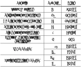
Table 1 Design specifications and circuit parameters
Quantity Symbol Value
Input DC voltage Ed 280 [V]
Series resonant capacitance Cr 0.49 [µF]
ZCS inductive snubber value Ls 12.0 [µH]
Self inductance of work coil L1 90.0[µH]
Time constant of the load τ 9.23[µ] Electro Magnetic coupling
co-efficient κ 0.48
VCE 600 [V]
IGBT(TO-3P)
IC 75 [A]
VRM 600 [V]
Antiparallel diode (TO-3P)
I0 30 [A]
mode 1 mode 2 mode 3 mode 4 mode 5 mode 6
i
Lv
Q2i
Q2v
Q1i
Q1 t0 t1t2t3t4t5t6 -50 -25 0 25 50 -400 -200 0 200 400 -50 -25 0 25 50 -400 -200 0 200 400 -50 -25 0 25 50mode 1 mode 2 mode 3 mode 4 mode 5 mode 6
i
Lv
Q2i
Q2v
Q1i
Q1 t0 t1t2t3t4t5t6 -50 -25 0 25 50 -400 -200 0 200 400 -50 -25 0 25 50 -400 -200 0 200 400 -50 -25 0 25 50mode 1 mode 2 mode 3 mode 4 mode 5 mode 6
i
Lv
Q2i
Q2v
Q1i
Q1 t0 t1t2t3t4t5t6 -50 -25 0 25 50 -400 -200 0 200 400 -50 -25 0 25 50 -400 -200 0 200 400 -50 -25 0 25 50mode 1 mode 2 mode 3 mode 4 mode 5 mode 6
i
Lv
Q2i
Q2v
Q1i
Q1 t0 t1t2t3t4t5t6 -50 -25 0 25 50 -400 -200 0 200 400 -50 -25 0 25 50 -400 -200 0 200 400mode 1 mode 2 mode 3 mode 4 mode 5 mode 6
i
Lv
Q2i
Q2v
Q1i
Q1 t0 t1t2t3t4t5t6 -50 -25 0 25 50 -400 -200 0 200 400 -50 -25 0 25 50 -400 -200 0 200 400 -50 -25 0 25 50Fig.6 Voltage and current waveforms in steady state of power injection
v
Li
L (a) Dp=0.2v
Li
L (b) Dp=0.8vL:500[V/div], iL:40[A/div], t: 400[µsec/div]
Fig.7 Experimental waveforms of vL and iL
for PDM duty cycle
utility AC power source grid. The single phase PFC converter with boost chopper can be conveniently used in place of diode rectifier. This high frequency inverter consists of the active power switches Q1 and Q2 are the switching power blocks
composed of the power semiconductor switches (IGBTs); SW1
and SW2 with antiparallel diodes; D1 and D2; Cr as a series
tuned resonant capacitor; Ls1 and Ls2 as an auxiliary
ZCS-assisted inductive lossless snubbers connected in series with Q1 and Q2 and the induction heated fixing drum roller
represented by the transformer circuit modeling. In this high frequency inverter circuit, the active power switches Q1 and
Q2 can operate completely under ZCS principle and its power
regulation based on variable pulse frequency modulation for both turn-on and turn-off mode zero current soft switching commutations. The effective output power of the high frequency inverter in Fig.4 can be newly regulated by a constant high frequency PDM control strategy on the basis of the principle in Fig.5. The circuit block surrounded by the dotted line is the transformer model parameters represented by the circuit parameters; unmeasurable (L1, L2 k, R2) or
measurable parameters (L1, k =M L1L2, τ=L2 R2) of the
IH load comprised of the working coil and induction heated fixing roller load displayed in Fig.2.
3.2 Circuits configuration
Since the geometric placement of the induction heated fixing rolling drum with working coil inserted inside the drum roller gives loose coupling coefficient k<1 for the induction heating, the magnetic coupling coefficient between the fixed working coil and rolling drum load is relatively poor became of large air gap. The high frequency series load resonant inverter circuit topology with series capacitor compensated resonant load tank with Cr is introduced in Fig.4. The DC bus
line ports of high frequency inverter is connected to the single phase diode rectifier with low pass filter; Lf & Cf.
Pulse density modulation controlled high frequency resonant inverter operation in ZCS commutation can be divided into two modes; continuous load current operating mode and discontinuous current operating mode in which the working frequency fs of the high frequency inverter in Fig.4 is
smaller than series resonant frequency
(
)
r d r LC
f <1 2π determined by the series resonant tank load. Although ZCS commutation mode can be provided for the discontinuous current operation without the auxiliary inductive snubbers in series with Q1 and Q2, extremely high peak currents across the
active power switches and high peak voltage on the resonant series compensated capacitor become serious problem for high output power setting of this high frequency inverter.
The developed series load resonant inverter can operate in continuous load resonant current mode that provides the soft commutation operation in ZCS and ZVS at the turn-off mode transitions. As for turn-on mode transition, hard switching commutation for Q1 and Q2 would occur if no modifications
due to the lossless inductive snubber topologies are made. Therefore, two extremely small inductor snubbers are connected in series with the active power switches Q1 and Q2
that provide complete ZCS condition for turn-on commutation. Thus, because of the lossless inductive snubbers, the soft switching commutation can be achieved both for turn-on and turn-off mode transitions. Furthermore, since the power losses caused by tail current and fall current of MOS gate controlled bipolar mode power semiconductor switches like IGBTs during turn-off period is likely to disappear in the circuit topology that can operate under the principle of ZCS, the proposed ZCS-PDM series resonant inverter is rather preferable to load resonant inverter ZVS scheme.
3.3 Pulse density modulation controlled power regulation
As shown in Fig.5, the power regulation can be achieved by varying the pulse density modulation with time ratio during
Ton period, when the output power is injected into the
induction heated load and a period Toff, when the output power
is non-injected into the induction heated load. With the changing the PDM time ratio, the of the applied pulse density ratio is taking place while the working frequency of the high frequency inverter is kept constant under a condition of zero current soft switching transition commutation.
The auxiliary inductive snubbers; Ls1 and Ls2 (Ls1= Ls2=Ls)
in series with the switches provide ZCS operation for Q1 and
Q2 in the continuous load current mode which is based on the
overlapping current in (SW1, D2) and (SW2, D1).
Since a complete ZCS operation for Q1 and Q2 is provided
over whole power regulating ranges, the high frequency leak current related electromagnetic noise and switching power losses for Q1 and Q2 are kept to be low. Furthermore, as
compared with the series load resonant inverters driven by the other control methods of PFM, PWM and PAM for the light induction heated load, almost no power losses is consumed during the power non-injected period in this high frequency
0 0.1 0.2 0.3 0.4 0.5 0.6 0.7 0.8 0.9 1 0 300 600 900 1200 70 75 80 85 90 95 100
Pulse density modulation ratio Dp
Inverter power [W ] Inverters efficiency [% ] Inverter input Inverter output Inverter efficiency
Fig.10 Power regulation characteristics in experimence
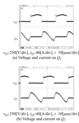
vQ1
iQ1
vQ1:250[V/div], iQ1:40[A/div], t: 10[µsec/div]
(a) Voltage and current on Q1
vQ2
iQ2
vQ2:250[V/div], iQ2:40[A/div], t: 10[µsec/div]
(b) Voltage and current on Q2
Fig.8 Experimental waveforms of switch voltage and current
vQ1
iQ1
vQ1:250[V/div], iQ1:20[A/div], t: 20[µsec/div]
(a) Voltage and current on Q1
vQ2
iQ2
vQ2:250[V/div], iQ2:20[A/div], t: 20[µsec/div]
(b) Voltage and current on Q2
Fig.9 Experimental waveforms of switch voltage and current at the beginning of the power injection period inverter, therefore, almost the same inverter efficiency is
observed as well as heavy induction heated load. 3.4 Circuit operation waveforms The voltage and current operation waveforms of the series load resonant inverter circuit shown in Fig.5 during the power injection period are illustrated in Fig.6.
The circuit parameters of the voltage source type PDM controlled high-frequency ZCS inverter using IGBTs are indicated in Table 1. Two auxiliary inductive snubbers Ls are
adjusted so as to be 12µH to provide the switch peak voltage 350V that includes ascertain tolerance to the limited standard parameters of the chosen IGBTs. In this case, the dynamic switch current stress di/dtmax becomes 12.5A/µs and current
overlapping time tu is set to 3.8µs.
4. EXPERIMENTAL RESULTS
The developed high-frequency series resonant inverter uses IGBTs (Mitsubishi Electric Co., Ltd., CT75AM-12) with soft-recovery diodes (Origin Electric Co. Ltd, US30P) as the antiparallel fast recovery diodes. For pulse density modulation ratio Dp=0.2 and Dp=0.8 in a PDM control scheme, the
measured operating waveforms of current iL and voltage vL are
depicted in Fig.7. Observed voltage and current waveforms
vQ1 & iQ1, vQ2 & iQ2 for the active power switches Q1 and Q2 in
switching arms of a SEPP type series resonant inverter of are shown in Fig.8.
The validity of the transformer type circuit models parameters of the induction heated fixing roller load in Fig.1 and Fig.2 is proven on the basis of these experimental results.
The voltage and current operating waveforms of the active power switches Q1 and Q2 during the beginning interval of
the power injection period are shown in Fig.9. It is clear that Q
1 and Q2 can operate under a condition of ZCS principle for
a PDM control implementation.
Figure 10 illustrates the pulse density modulation ratio vs. output power characteristics and pulse density modulation ratio Dp vs. power conversion efficiency characteristics for
series resonant high frequency inverter in Fig.4. The output effective power of the high frequency inverter treated here can be regulated and linearly by changing the pulse density modulation ratio Dp. For output power regulation ranges from
conversion efficiency more than 94% can be obtained by the breadboard setup. Especially, it is important that actual efficiency more than 94% is able to be achieved even for both
Dp=1.0 in copy machine printing mode and Dp=0.05 in its
stand-by mode, which make the proposed series resonant ZCS-PDM controlled high-frequency inverter effective for the induction heated fixing roller applications in copy and printing machine.
5. CONCLUSIONS
In this paper, the voltage-fed high-frequency half-bridge (single ended push-pull; SEPP) type series load resonant zero current soft switching inverter with ZCS-assisted two auxiliary inductive snubbers has been introduced for the induction-heated fixing roller in the copy and printing machines. Its steady state operation under PDM control scheme has been evaluated and discussed on the basis of simulation and experimental data.
The power regulating characteristics and operating performances of this simple SEPP series resonant high frequency inverter in steady state operation has been qualitatively evaluated in simulation and experiment. For the power loss estimations of this high frequency inverter, the transformer type circuit model of the induction-heated fixing roller in copy and printing machine has been used from a practical point of view.
The actual high efficiency more than 94% has been observed for all the output power regulation ranges from 50W to 1200W with stable soft switching operation and linear output power control characteristics under a condition of ZCS commutation. The SEPP type high frequency series resonant ZCS inverter with lossless inductive snubbers, which is based on a constant frequency PDM control scheme, has pointed out its practical effectiveness for the stand-by mode and printing mode. Furthermore, the power losses analysis of this high frequency inverter with a PDM control scheme has been analyzed using the approximated v-i characteristics of IGBTs and diodes used here.
REFERENCES
[1] H.Omori, M.Nakaoka: “Generic Circuit Topologies and Their Performance Evaluations of Single-Ended Resonant High-Frequency Inverter for Induction-Heated Cooking Appliances”, Trans. on IEE of Japan, Vol.117-D, No.2, February, 1997.
[2] B.K.Lee, J.W.Jung, B.S.Suh, D.S.Hyun: “A New Half-Bridge Inverter Topology with Active Auxiliary Resonant Circuit Using Insulated Gate Bipolar Transistors for Induction Heating Appliances”, Proceedings of IEEE-PESC (Poweer Electronics Specialists Conference), Vol.2, pp.1232-1237, June, 1997.
[3] P. R. Palmer, A. N. Githiari, “An MCT Based Industrial Induction Cooker Circuit Using Zero Current Switching,” Proceedings of EPE (European Power Electronics), pp.2.677-2.682, September, 1995.
[4] I.Hirota, H.Omori, S.Muraoka, S.Hishikawa, K.Nishida, E.Hiraki and M.Nakaoka: “Improved Quasi-Resonant ZVS-PWM Inverter with Active Voltage-Clamped Capacitor for Consumer Induction Heating”, Proceedings of IEEE-IAS IATC (International Appliance Technical Conference), pp.111-116, May, 2000.
[5] Monterde, Hernandez, R.Garcia, Martinez: “Comparison of Control Strategies for Series-Resonat Full-Bridge
Inverter for Induction Cookers”, Proceedings of The 8th
International Conference on EPE (European Power Electronics), Vol.1-4, pp.1-8(CD-ROM), Sept, 1999.
[6] Rafael Ordo.EZ and Hugo Calleja, “Induction Heating Inverter with Power Factor Correction”, Proceedings of IEEE CIEP (International Congress on Power Electronics), Oct, pp.90-95, October, 2002.
[7] S. Kubota, Y. Hatanaka, “A Novel High Frequency Power Supply for Induction Heating,” in Proc. of IEEE-PESC (Poweer Electronics Specialists Conference), Vol.1, pp.165-171, June, 1998.
[8] Y. Hatanaka, H. Kifune and T. Shimade, “A Novel ZCS High Frequency Inverter with Complex Resonance and Design Procedure for High Amplitude of Output Current,” Proceedings of IEEE-PEDS (Power Electronics and Drive Systems), Vol.1, pp.443-447, September, 2001.
[9] H. Fujita, H. Akagi, “Control and Performance of a Pulse-Density-Modulated Series-Resonant Inverter for Corona Discharge Processes,” IEEE Trans. on Industry Applications, Vol.35, No.3, pp.621-627, May/June, 1999.
[10] S. P. Wang, Y. Konishi, O. Koudriavtsev, M. Nakaoka, “Voltage-Fed Pulse Density and Pulse Width Modulation Resonant Inverter for Silent Discharge Type Ozonizer,” Trans. on IEE of Japan, Vol.120-D (J-IAS), No.4, pp.587-592, April, 2000.