P1-104 / J. W. Park
• IMID 2009 DIGEST
Abstract
Here we report another soft lithography, peel-off method, for patterning conductive polymer anodes in the fabrication of flexible ITO-free organic light-emitting diodes. This method doesn’t require any heating process and UV light. We have demonstrated that such a peel-off technique enables the formation of a very sharp edge and the enhancement of edge roughness.
1. Introduction
Organic light-emitting diodes (OLEDs) have attracted much attention due to their potential advantage of flexible display[1] and large-area lighting applications [2]. One of the key issues of flexible OLEDs is to form a transparent electrode on flexible substrates. Indium-tin-oxide (ITO) has been widely used as a transparent anode of flexible OLEDs, yet fails to provide stable anode properties mainly because of its brittleness[3] on flexible substrates. With attempt to replace ITO, extensive researches into organic-based electrode materials (e.g., polyaniline, polypyrrole, polythiophene, poly(3,4-ethylenedioxythiophene):poly(styrene sulfonate) (PEDOT:PSS), etc.) have been made [1]. Of those, PEDOT:PSS has many advantages of colorless transparency, high conductivity, easy variation of viscosity, easy deposition, low surface roughness, high flexibility, and low cost [4], [5]. However, patterning the PEDOT layer on flexible substrates should be feasible for the fabrication of ITO-free flexible OLEDs. Recently, soft lithography such as micro-contact printing [6], lift-up technique [7], and soft embossing [8], were suggested, all of which require a heating process. However, the use of UV light may cause material degradation and a heating process may not be suitable for flexible organic electronics. Therefore, new techniques for the fabrication of flexible OLEDs are needed. In this
study, we bring in another soft lithography, peel-off method, for patterning the polymer electrode on flexible substrates without any other process involved such as UV irradiation or heat treatment.
2. Experiment
For experiments, PEDOT:PSS (CELVIOSTM
PH500) was used as a polymeric anode material. The weight ratio of PEDOT to PSS was 1:2.5, and the mixture was diluted with H2O. We doped 7.5 wt%
DMSO into PEDOT:PSS to increase its conductivity as well as viscosity along with 0.625 wt% D-sorbitol as plasticizer [8]. The used flexible polymer substrate was polyethersufone (Glastic PES, I-components Co.). The PES film thickness was 0.1 mm, surface roughness was about 8 nm, and optical transmittance was 87 % at 500 nm. To enhance the uniformity of PEDOT:PSS films over a large area, we utilized the multi-step spin casting process. The spin coating speed at the first stage was 500 rpm for 20s, 1000 rpm at the second stage for 40s, and 3500 rpm at the final stage for 4min. With this approach, the thickness of the modified PEDOT:PSS layer was measured to be 180 nm, surface roughness was 2.2 nm, sheet resistance was 222 Ω/□, and optical transmittance was 88 % at 500 nm.
3. Results and discussion
Figure 1 shows the schematic diagram of the peel-off patterning method. Before spin coating the PEDOT:PSS solution on the PES substrate, we pre-coated the surfactant (polyoxyethylene (12) tridecylether) layer on the PES substrate so as to achieve uniform hydrophilic PEDOT:PSS layer coating on the hydrophobic PES substrate. We then attached the film peeler (adhesive film) to the
Patterning of Conductive Polymer Anodes
Using a Peel-off Method
Jongwoon Park, Younchan Yim, Giseok Heo, Jongho Lee,
Taewon Kim, and Gwangyoung Kim
Korea Institute of Industrial Technology, Oryong-dong, Gwangju, Seoul 500-480, Korea Tel.:82-62-600-6520, E-mail: [email protected]
P1-104 / J. W. Park
IMID 2009 DIGEST •
PEDOT:PSS anode using a roller. The desired pattern geometry could be formed on the film peeler. Upon lifting the film peeler up, the polymer anode is peeled off since the adhesion energy between the film peeler and the PEDOT:PSS anode is higher than that between the surfactant layer and the flexible substrate. When the adhesion energy between the film peeler and the PEDOT:PSS layer is lower than that between the surfactant layer and the flexible substrate, however, patterning the PEDOT:PSS anode may not be feasible.
Fig. 1. Generic process flow for peeling off polymeric anode spin coated on a flexible substrate.
Fig. 2. (a) 2-D and (b) 3-D AFM images of the patterned PEDOT:PSS anode near the boundary line
Shown in Fig. 2(a) is 2-D atomic force microscopy (AFM) image. The patterned boundary line is clearly visible, indicating that the edge sharpness is expected to be high. It is indeed observed from 3-D AFM image in Fig. 2(b) that the pattern edge is very steep. After the peeling-off process, however, the remaining polymer near the boundary line may be detached from the substrate [7], thereby degrading the edge roughness. With the material system chosen here, such a phenomenon appears imperceptible, as demonstrated in the inset in Fig. 2(b).
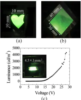
Fig. 3. Snapshots of EL emission from (a) the heart-shaped and (b) large-area (40 mmⅹ30 mm) rectangular green OLEDs, and (c) measured luminance from the 4.5 mmⅹ3 mm green OLED as a function of bias voltage.
On the basis of the peel-off patterning method, we have successfully fabricated three flexible green OLEDs via a solution process. Those OLED structures consist of a 180-nm-thick PEDOT:PSS anode coated on a 0.1-mm-thick PES substrate, a 80-nm-thick phosphorescent light emitting layer containing Ir complex, a 1-nm-thick electron-injecting interfacial layer of lithium fluoride (LiF), and a vacuum evaporated 80-nm-thick aluminum (Al) cathode deposited sequentially. Shown in Figs. 3(a) and (b) are snapshots of electroluminescence (EL) emission from the heart-shaped OLED and large-area (40 mmⅹ30 mm) rectangular OLED, respectively. Uniform light emission was obtained from the heart-shaped OLED, whereas a noticeable voltage drop was observed from the large-area rectangular OLED due to high resistance of the polymer anode. Presented in Fig. 3(c) is the measured luminance from a 4.5 mmⅹ3 mm green OLED as a function of bias voltage. The peak luminance was measured to reach 4,315 cd/m2,
which is relatively high from a solution-processed ITO-free flexible OLED. From these results, one may conclude that the peel-off method allows the formation of the polymer anode with not only the straight line patterns but also the curved patterns, demonstrating the potential use of the peel-off method for flexible OLEDs in various shapes.
P1-104 / J. W. Park
• IMID 2009 DIGEST
4. Summary
We have employed the peel-off method to pattern the PEDOT:PSS anode spin coated on a flexible substrate. It has been shown that patterning the polymer anode is feasible given that the adhesion energy between a film peeler and a polymer anode is higher than that between a surfactant layer and a flexible substrate. With the peel-off method, the formation of a very sharp edge and the suppression of edge roughness near the patterned boundaries have been achieved. Furthermore, we have successfully fabricated ITO-free flexible green OLEDs via a solution process and obtained the luminance as high as 4,000 cd/m2, demonstrating the potential use of the
peel-off method for the fabrication of flexible OLEDs.
Acknowledgement
This work was supported by Korea Institute of Industrial Technology. [09-IK-2-0002, Development of Transparent Conducting Polymer for OLED Applications]
5. References
1. G. P. Grawford, Flexible Flat Panel Displays (Wiley, England, 2005)
2. J. W. Park, J. H. Lee, D. C. Shin, and S. H. Park, IEEE J. of Display Technol., (to be published) 3. L. Ke, R. S. Kumar, S. J. Chua, and A. P. Burden,
Appl. Phys. A. Vol. 81, p.969 (2005)
4. K. Fehse, K. Walzer, K. Leo, W. Lövenich, and A. Elschner, Adv. Mater. Vol. 19, p.441 (2007)
5. S. I. Na, S. S. Kim, J. Jo, and D. Y. Kim, Adv. Mater., Vol. 20, p.1 (2008)
6. A. Kumar and G. M. Whitesides, Appl. Phys. Lett., Vol. 63, p.2002 (1993)
7. T. Granlund, T. Nyberg, L. S. Roman, M. Svensson, and O. Inganäs, Adv. Mater. Vol. 12, p.269 (2000) 8. L. S. Roman, O. Inganäs, T. Granlund, T. Nyberg,
M. Svensson, M. R. Adersson, and J. C. Hummelen, Adv. Mater. Vol. 12, p.189 (2000)