32ND INTERNATIONAL COSMIC RAY CONFERENCE,BEIJING 2011
Overview of the JEM-EUSO Instruments
F.KAJINO1,P.PICOZZA2,11,T.EBISUZAKI2,H.MASE2,K.TSUNO2,Y.TAKIZAWA2,Y.KAWASAKI2,K.SHINOZAKI2,
H.OHMORI2,S.WADA2,N.INOUE3,N.SAKAKI4,J.ADAMS5,M.CHRISTL5,R.YOUNG5,C.FERGUSON5,M.BONAMENTE6, A.SANTANGELO7,M.TESHIMA8,E.PARIZOT9,P.GORODETZKY9,O.CATALANO10,M.CASOLINO11,M.BERTAINA12, M.PANASYUK13,B.A.KHRENOV13,I.H.PARK14,A.NERONOV15,G.MEDINA-TANCO16,D.RODRIGUEZ-FRIAS17, J.SZABELSKI18,P.BOBIK19 AND R.TSENOV20 ON BEHALF OF THE JEM-EUSO COLLABORATION
1
Department of Physics, Konan University, Okamoto 8-9-1, Higashinada, Kobe 658-8501, Japan
2
RIKEN Advanced Science Institute, 2-1 Hirosawa, Wako351-0198, Japan
3
Graduate School of Science and Engineering, 255 Shimo-Okubo, Sakura-ku, Saitama City, Saitama 338-8570, Japan
4
Department of Physics and Mathematics, Aoyama Gakuin University, 5-10-1 Fuchinobe, Chuo-ku, Sagamihara-shi, Kanagawa 252-5258, Japan
5
NASA Marshall Space Flight Center, Huntsville, AL 35812, USA
6
Department of Physics, University of Alabama, Huntsville, AL35899
7
Astronomie und Astrophysik, Universitt Tubingen, Sand 1, 72076 Tubingen, Deutschl
8
Institute of Cosmic Ray Research, University Tokyo, Kashinoha 5-1-5, Kashiwa, Chiba 277-8582, Japan
9
APC, Univ. of Paris Diderot, CNRS/IN2P3, 10, rue A. Domon et L. Duquet, 75205 Paris Cedex 13, France
10
Istituto di Astrofisica Spaziale e Fisica Cosmica di Palermo, INAF, Via Ugo La Malfa 153, 90146 Palermo, Italy
11
Department of Physics, University of Rome Tor Vergata, Via della Ricerca Scientifica 1, 00133 Rome, Italy
12
Dipartimento di Fisica Generale, Università di Torino,Via Giuria 1 10125 Torino, Italy
13
SINP, Lomonosov Moscow State Univ., Leninskie Gory 1 str. 2, Moscow, 119991, Russia
14
Department of Physics, Ewha Womans University, Seoul 120-750, Korea
15
ISDC, Data Centre for Astrophysics, Chemin d’Ecogia 16, CH-1290 Versoix ,Switzerland
16
Inst. de Ciencias Nucleares, UNAM, AP 70-543 / CP 04510, Mexico D.F.
17
Soltan Institute for Nuclear Studies, 90-950 Lodz, Box 447, Poland
18
University of Alcala Ctra. Madrid-Barcelona, km. 33.6, E-28871, Alcala de Henares, Madrid. Spain
19
Institute of Experimental Physics SAS, Watsonova 47, 040 01 Kosice, Slovakia
20
St. Kliment Ohridski University of Sofia, 5, James Bourchier Boul., SOFIA 1164, Bulgaria
kajino@konan-u.ac.jp
Abstract: JEM-EUSO mission with a large and wide-angle telescope to be mounted on the International Space Sta-tion has been planned to open up "particle astronomy" through the investigaSta-tion of extreme-energy cosmic rays by detecting fluorescent and Cherenkov photons generated by air showers in the earth's atmosphere. The JEM-EUSO telescope consists of 3 light-weight optical Fresnel lenses with a diameter of about 2.5m, 300k channels of MAPMTs, frontend readout electronics, trigger electronics, and system electronics. An infrared camera and a LIDAR system will be also used to monitor the earth's atmosphere.
Keywords: cosmic rays, air shower, JEM-EUSO, telescope, International Space Station, ISS, JEM
1 Introduction
JEM-EUSO on board the International Space Station(ISS) is a new type of observatory which uses the whole Earth as a detector. Extreme-energy cosmic rays (EECR)
AUTHOR ET AL. PAPERSHORT TITLE
2
coming to the earth's atmosphere collide with atmospher-ic nuclei and produce extensive air showers (EAS). Charged particles in EAS excite nitrogen molecules and emit near ultra-violet (UV) photons. They also produce Cherenkov photons in a narrow cone of about trajectory of the EAS. JEM-EUSO mission observes these photons from the ISS orbit at an altitude of about 400 km. Re-flected Cherenkov photons at the ground are observed as a strong Cherenkov mark. Viewing from the ISS orbit, the Field-of-View of the telescope (±30°) corresponds to the observational area at the ground larger than 1.9 × 10⁵ km2.
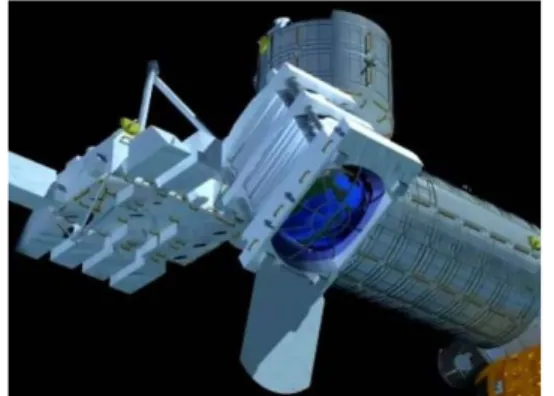
Threshold energy to detect EECRs is as low as several × 1019 eV. Increase in exposure is realized by inclining the telescope from nadir to tilted mode, though the threshold energy becomes higher. (Figure 1) The first half of the mission lifetime is devoted to observe lower energy cos-mic rays with the nadir mode and the second half to ob-serve higher energies by the tilted mode. JEM-EUSO will be launched by H2B rocket and conveyed by H-II Transfer Vehicle (HTV) to ISS. It will be attached to the Exposure Facility (EF) of the Japanese Experiment Module (JEM) [1,2,3].
Details of JEM-EUSO mission, science objectives, re-quirements and expected performances are reported in [4,5,6].
Figure 1. Illustration of the JEM-EUSO telescope on the ISS for the tilted observation mode.
2 JEM-EUSO System
Overall JEM-EUSO system consists of a flight segment, a ground support equipment and a ground segment, which is shown in Figure 2.
Figure 2. Overall JEM-EUSO System.
The flight segment consists of a science instrument sys-tem and a bus syssys-tem. The science instrument syssys-tem basically consists of the following systems:
1) The JEM-EUSO telescope which is a large diameter telescope to observe EECR
2) Atmospheric monitoring system 3) Calibration system
Details of these systems are described in the following sections.
The ground support equipment (GSE) consists of me-chanical, electrical, optical, calibration GSE. GSE sup-ports manufacturing the flight segment.
The ground segment (GS) consists of a ground based calibration system, a launch site operation, a mission operation control and a science data center. GS supports launching and mission operation, data calibration while the mission is in operation by using many flashers and LIDARs which are installed on the ground. Science data analysis is also included in GS.
2.1 The JEM-EUSO telescope
The JEM-EUSO telescope is an extremely-fast, highly-pixelized, large-aperture and large-FoV digital camera, working in near-UV wavelength range (330÷400 nm) with single photon counting capability. The telescope mainly consists of four parts: collecting optics, focal surface detector, electronics and structure. (Figure 3, 4)
Figure 3. Side view of the JEM-EUSO telescope.
Figure 4. Bottom view of the JEM-EUSO telescope. The optics focuses the incident UV photons onto the focal surface with an angular resolution of 0.1°. The
32ND INTERNATIONAL COSMIC RAY CONFERENCE ,BEIJING 2011 3 focal surface detector converts the incident photons to
electric pulses. The electronics counts the number of the pulses in a period less than 2.5 s and records it as a brightness data. When a signal pattern of an EAS is found, trigger is issued. This starts a sequence to send the brightness data of the triggered (and surrounding) pixels to the ground operation center. The structure encloses all the parts of the instruments and keeps them out from the outer harmful environment in space. It also keeps the optical lenses and the focal surface detector to the preset place. The telescope is stowed when it is launched and deployed in the observation mode. Main parameters of the JEM-EUSO telescope are summarized in Table 1.
Table 1. Parameters of JEM-EUSO telescope Field of View
Observational area Optical bandwidth Focal Surface area Number of pixels Pixel size
Pixel size at ground Spatial resolution Event time sampling Duty cycle ± 30° > 1.9 × 10⁵ km2 330÷400 nm 4.5 m2 3.2 ×10⁵ 2.9 mm ~ 550 m 0.07° 2.5 s ~ 20 %
Total mass of the instruments is 1983 kg and electric power is suppressed less than 1kW in operation mode.
2.2 Optics
Two curved double sided Fresnel lenses with 2.65m external diameter, a precision middle Fresnel lens and a pupil constitute optics of the JEM-EUSO telescope. The Fresnel lenses can provide a large-aperture, wide FoV optics with low mass and high UV light transmittance. Combination of 3 Fresnel lenses realizes a full angle FoV of 60° and an angular resolution of 0.07°. This resolution corresponds approximately to 550 m on the earth. The material of the lens is CYTOP and UV transmitting PMMA which has high UV transparency in the wave-length from 330nm to 400nm. A precision Fresnel optics adopting a diffractive optics technology is used to sup-press the color aberration. Details are described in [7,8,9].
2.3 Focal Surface Detector
The focal surface (FS) of JEM-EUSO has a spherical surface of about 2.3 m in diameter with about 2.5 m curvature radius, and it is covered with about 5,000 mul-ti-anode photomultiplier tubes [10]. The FS detector consists of Photo-Detector Modules (PDMs), each of which consists of 9 Elementary Cells (ECs). The EC contains 4 units of MAPMT. 137 PDMs are arranged in FS (Figure 5) [11].
Cockcroft-Walton type high-voltage supply will be used to suppress power consumption, which includes a circuit to protect MAPMT from an instantaneous large amount of light like lightning [12].
The MAPMTs developed for the JEM-EUSO mission are going to be tested by Russian space mission, TUS detec-tor [13].
Figure 5. Illustrated images of air showers generated by EECR for various incident angles and positions on the focal surface detector.
2.4 Focal Surface Electronics
The FS electronics system records the signals of UV photons generated by EECRs successively in time. A new type of frontend ASIC has been developed for this mis-sion, which has both functions of single photon counting and charge integration in a chip with 64 channels [14,15]. The system is required to keep high trigger efficiency with a flexible trigger algorithm [16] as well as a reason-able linearity over 1019-1021 eV range. The requirements of very low power consumption must be fulfilled to man-age 3.2×10⁵ signal channels. Radiation tolerance of the electronic circuits in the space environment is also re-quired.
The FS electronics is configured in three levels corre-sponding to the hierarchy of the FS detector system: front-end electronics at an EC level, PDM electronics common to 9 EC units, and FS electronics to control 137 units of PDM electronics. Anode signals of the MAPMT are digitized and recorded in ring memories for each Gate Time Unit (=2.5s) to wait for a trigger assertion, then, the data are read and are sent to control boards. JEM-EUSO uses hierarchical trigger method to reduce huge original data rate of ~10GB/s to 297 kbps for send-ing data from ISS to ground operation center [17,18].
2.5 Monitoring/Control Electronics
System control electronics consists of Data Processor (DP), Mission Data Processor (MDP) and Movement Controller (MC). Main functions of DP are: a) Commu-nication with MDP, MC and JEM/EF, b) House Keeping (HK) data acquisition related to mission system [19], c) Interface function which distributes clock signal from GPS to MDP [20]. MDP acquires observation data from FS detector, atmospheric monitor and HK data, and then sends data to DP. MC accepts signals from DP and con-trols movable mechanisms.
AUTHOR ET AL. PAPERSHORT TITLE
4
2.6
Atmospheric Monitoring System
Atmospheric Monitoring System (AM) monitors the earth's atmosphere [21]. Intensity of the fluorescent and Cherenkov light emitted from EAS at JEM-EUSO de-pends on the transparency of the atmosphere, the cloud coverage and the height of cloud top, etc.. These must be determined by AM of JEM-EUSO. In case of events above 1020 eV, the existence of clouds can be directly detected by the signals from the EAS. However, the monitoring of the cloud coverage by AM is important to estimate the effective observing time with high accuracy and to increase the confidence level [22,23,24]. The AM consists of the followings: 1) Infrared camera [25], 2) LIDAR, 3) Slow data of the JEM-EUSO telescope.
2.7 Calibration System
The calibration system measures the efficiencies of the optics, the focal surface detector and the data acquisition electronics with a precision necessary to determine ener-gy and arrival direction of EECR [26]. The calibration system consists of the following categories: 1) Pre-flight calibration, 2) On-board calibration, 3) Calibration in flight with on-ground instruments, 4) Atmospheric moni-tor calibration.
The pre-flight calibration of the detector will be done by measuring detection efficiency, uniformity, gain etc. with UV LED's. To measure efficiencies of FS detector, sever-al diffuse LED light sources with different wavelengths in the near UV region are placed on the support of the rear lens before FS. To measure efficiencies of the lenses similar light source is placed at the center of FS. Reflect-ed light at the inner surface of the lid is observReflect-ed with FS. In this way, the gain and the detection efficiency of the detector will be calibrated on board.
The system can be calibrated with 10-20 ground light sources when JEM-EUSO passes over them. The amount of UV absorption in the atmosphere is measured with Xe flasher lamps. The systematic error in energy and direc-tion determinadirec-tion will be empirically estimated, by observing emulated EAS images with a UV laser by the JEM-EUSO telescope. The transmittance of the atmos-phere as a function of height will be also obtained. The IR camera as a FoV monitoring system takes pic-tures periodically in observation and the effective area will be estimated [23].
2.8 Structure Analysis
To accommodate JEM-EUSO into a volume of the HTV transfer vehicle, a contractible/extensible structure is adopted. The structure is stowed at launch by H2B rocket and it is extended at JEM/EF of ISS. Structure analysis for vibration showed that the minimum natural frequency for launch mode was 25.6 Hz and that for the observation mode it was as low as 1.7 Hz. Both of them satisfied the requirements.
3 Conclusion
Phase A study (feasibility study and conceptual design) of the JEM-EUSO mission started in 2007. Many new technological items have been developed to realize the mission by inheriting ESA-EUSO. The study is now successfully in progress with an international collabora-tion of 13 countries.
Acknowledgments
This work was supported in part by Grants-in-Aid for Science Research from the Japan Society for the Promo-tion of Science in Japan.
References
[1] Y. Takahashi et al., New Journ. of Phys. 11, 065009, 2009
[2] T. Ebisuzaki et al., Nucl. Phys. B (Proc. Suppl.), 175-176, 237, 2008
[3] F. Kajino et al. (JEM-EUSO collab.), Nucl. Instr. Meth. A 623, 422-424, 2010.
[4] T. Ebisuzaki et al., Proc. 32nd ICRC, 2011 (ID1628). [5] G. Medina-Tanco et al., Proc. 32nd ICRC, 2011 (ID0956).
[6] A. Santangelo et al., Proc. 32nd ICRC, 2011 (ID0991). [7] A. Zuccaro et al., Proc. 32nd ICRC, 2011 (ID0852). [8] Y. Takizawa et al., Proc. 32nd ICRC, 2011 (ID0874). [9] J. Adams et al., Proc. 32nd ICRC, 2011 (ID1100). [10] Y. Kawasaki et al., Proc. 32nd ICRC, 2011 (ID0472). [11] M. Ricci et al., Proc. 32nd ICRC, 2011 (ID0335). [12] J. Karczmarczyk, et al., Proc. 32nd ICRC, 2011 (ID0216).
[13] B. Khrenov et al., Proc. 32nd ICRC, 2011 (ID1261). [14] S. Ahmad et al., Proc. 32nd ICRC, 2011 (ID0236). [15] H. Miyamoto et al., Proc. 32nd ICRC, 2011 (ID0775). [16] O. Catalano et al., Proc. 31st ICRC, 2009 (ID0326). [17] J. Bayer et al., Proc. 32nd ICRC, 2011 (ID0836). [18] M. Casolino et al., Proc. 32nd ICRC, 2011 (ID1219). [19] G. Medina-Tanco et al., Proc. 32nd ICRC, 2011 (ID0961).
[20] G. Osteria et al., Proc. 32nd ICRC, 2011 (ID1131). [21] A. Neronov et al., Proc. 32nd ICRC, 2011 (ID0301). [22] F. Garino et al., Proc. 32nd ICRC, 2011 (ID0398). [23] A. Anzalone et al., Proc. 32nd ICRC, 2011 (ID1152). [24] G. Saez et al., Proc. 32nd ICRC, 2011 (ID1034). [25] J.A. Morales et al., Proc. 32nd ICRC, 2011 (ID1031). [26] P. Gorodetzky et al., Proc. 32nd ICRC, 2011 (ID0218).