저작자표시-비영리-변경금지 2.0 대한민국 이용자는 아래의 조건을 따르는 경우에 한하여 자유롭게 l 이 저작물을 복제, 배포, 전송, 전시, 공연 및 방송할 수 있습니다. 다음과 같은 조건을 따라야 합니다: l 귀하는, 이 저작물의 재이용이나 배포의 경우, 이 저작물에 적용된 이용허락조건 을 명확하게 나타내어야 합니다. l 저작권자로부터 별도의 허가를 받으면 이러한 조건들은 적용되지 않습니다. 저작권법에 따른 이용자의 권리는 위의 내용에 의하여 영향을 받지 않습니다. 이것은 이용허락규약(Legal Code)을 이해하기 쉽게 요약한 것입니다. Disclaimer 저작자표시. 귀하는 원저작자를 표시하여야 합니다. 비영리. 귀하는 이 저작물을 영리 목적으로 이용할 수 없습니다. 변경금지. 귀하는 이 저작물을 개작, 변형 또는 가공할 수 없습니다.
Thesis for the Degree of Doctor of Philosophy
Cellulose Nanofiber Matrix-Assisted
3D Printing
셀룰로오스 나노섬유 매트릭스 지지
3 차원 프린팅
February 2020
Seoul National University
Department of Biosystems & Biomaterials
Science and Engineering
i
Abstract
Cellulose nanofibers (CNFs) are attracting material for a three-dimensional (3D) printing matrix due to excellent rheological characteristics. In 3D printing with CNFs, a nozzle moves through the viscoelastic CNF matrix and makes patterns with ink materials. Rheological properties of CNFs are related to various factors including fiber dimension and concentration of CNFs in the aqueous dispersion, and influence on the printing fidelity. The different morphology of CNFs was prepared by varying the degree of carboxymethylation with CNFs. The printing fidelity was evaluated by observing the shape of ink features that were printed directly inside the CNF matrix. The relationship between the rheological properties of the CNF matrix and the printing fidelity was investigated on the printing speed, strain fields, and yielded regions. The cell-containing bio-ink and hydrophobic silicon-based inks were printed in the CNF matrix in a complex structure with high printing fidelity.Amazingly, the structure printed freely in the CNF hydrogels was able to retain its highly resolved 3D features in an ultrathin two-dimensional (2D) paper using a simple drying process. The two-dimensional change in the CNF hydrogels from 3D to 2D resulted from simple dehydration of the CNFs and provided transparent, stackable paper-based 3D channel devices. The CNF devices exhibited selective diffusion of molecules from the channel wall, indicating the applicability for the sensor and the cell culture platforms.
Keyword: Matrix-assisted 3D printing, cellulose nanofiber, microfluidic
device, rheology
ii
Table of Contents
Abstract ... i Table of Contents ... ii List of Figures ... v Ⅰ. Introduction ... 1 Ⅱ. Literature Survey ... 42.1. Various 3D printing technologies ... 4
2.2. Matrix-assisted 3D printing (MAP) ... 8
2.2.1. Rheological requirements for MAP ... 10
2.2.2. Various matrix systems for MAP ... 11
2.3. Cellulose ... 16 2.3.1. Cellulose nanofiber (CNF) ... 17 2.3.2. Extraction methods of CNF ... 18 2.3.3. Rheological properties of CNF ... 21 2.4. CNF as a 3D printing material ... 23 2.4.1. CNF as a rheology modifier ... 23 2.4.2. CNF as a reinforcement... 24 2.5. CNF based devices ... 27
2.5.1. Transparent and thin device through dehydration ... 27
2.5.2. Electronic devices ... 28
2.5.3. Biological and chemical sensing devices ... 29
2.5.4. Cell culture devices ... 30
Ⅲ. Materials and Methods ... 32
3.1. Preparation and characterization of the CNF matrix ... 32
iii
3.2.1. Cross-linked polyacrylic acid-based model ink ... 33
3.2.2. CNF based bio-ink ... 34
3.2.3. Petroleum-jelly based removable ink ... 34
3.2.4. Silicone ink-based curable ink ... 34
3.3. Rheological properties of CNF matrices and inks ... 35
3.4. Matrix-assisted 3D printing of a single line ... 35
3.4.1. Matrix-assisted 3D printing of straight line ... 35
3.4.2. Matrix-assisted 3D printing of angled line ... 36
3.5. Matrix-assisted 3D printing of multi-lines ... 36
3.5.1. Matrix-assisted 3D printing of multi-lines ... 36
3.5.2. Particle Image Velocimetry (PIV) test ... 36
3.6. Living cell embedded bio-ink printing ... 37
3.7. Silicone actuator printing ... 37
3.8. Fabrication of CNF based open-channel microfluidic devices ... 38
3.8.1. Fabrication process of CNF microfluidic devices ... 38
3.8.2. CNF based pH sensor ... 39
3.8.3. CNF based heavy metal sensor ... 39
3.9. Fabrication of CNF based open cell culture platform ... 40
3.9.1. Hydrophobic treatment of CNF... 40
3.9.2. Mass transfer test at the CNF layers... 41
3.9.3. Cell culture on CNF microfluidic devices... 41
3.10. Imaging ... 42
Ⅳ. Results and Discussion ... 43
4.1. Properties of carboxymethylated CNF matrix ... 43
4.2. Rheological properties of CNF matrix ... 52
4.2.1. Shear-thinning property of CNF matrix ... 52
4.2.2. Yielding property of CNF matrix ... 55
iv
4.3. Evaluation of printing fidelity in a single printing line feature ... 60
4.3.1. Evaluation of printing fidelity by sharpness of angled-line ... 60
4.3.2. Evaluation of printing fidelity by cross-sectional ratio ... 66
4.3.3. Evaluation of printing fidelity by straightness of line surface ... 69
4.3.4. Evaluation of printing fidelity with hydrophobic ink... 74
4.4. Evaluation of printing fidelity in multi printing lines feature ... 82
4.4.1. Particle image velocimetry (PIV) test ... 82
4.4.2. Velocity magnitude around nozzle ... 86
4.4.3. Matrix composition and printing path effects on fidelity ... 88
4.5. Printing of various ink materials ... 90
4.5.1. Rheological properties of various ink materials ... 90
4.5.2. Living cell embedded 3D bio-printing ... 92
4.5.3. Feasibility test of printed silicone actuator ... 92
4.6. Fabrication of CNF based open-channel microfluidic devices ... 95
4.6.1. Feasibility test of microfluidic channel devices ... 97
4.6.2. Control of channel diameters ... 99
4.6.3. Dimension control of the microfluidic device ... 101
4.6.4. Feasibility of pH sensor ... 103
4.6.5. Colorimetric analysis of heavy metal ions ... 105
4.7. Fabrication of CNF based open cell culture platform ... 107
4.7.1. Evaluation of hydrophobicity of MTMS treated CNF ... 111
4.7.2. Diffusion of FITC-Dex to CNF channel layers ... 114
4.7.3. Cell viability of the CNF-based platform ... 117
4.7.4. Effect of cisplatin at the CNF-based platform ... 118
Ⅴ. Conclusion ... 121
v
List of Figures
Figure 1. Common light- and ink-based 3D printing methods. (a) The light-based 3D printing method known as continuous liquid interface production. (b) Light-based selective laser sintering of powders. (c) Light- and ink-based photocurable inkjet printing of photopolymerizable resins. (d) Ink-based fused deposition modeling of thermoplastic filaments. (e) Direct ink writing using viscoelastic inks. ... 7 Figure 2. Schematic illustration of matrix-assisted 3D printing (MAP)... . 9 Figure 3. Various matrix systems for MAP. (a) Fluorescent image of a 3D microvascular network fabricated via omnidirectional printing of a fugitive ink (dyed red) within a photopolymerized Pluronic F127-diacrylate matrix. (b) Confocal images of a filament of a fluorescein-labeled ink and then a continuous spiral of a second, rhodamine-fluorescein-labeled ink printed into a self-healing hydrogel matrix. (c) A dark-field image of the arterial tree mounted in a perfusion fixture to position a syringe in the root of the tree. (d) A thin-shell model octopus is made from multiple connected hydrogel parts in a cross-linked acrylic acid matrix. (e) Optical image of matrix-assisted 3D printed architectures, including a body-centered cubic lattice. (f) Macroscopic image of a perfusable network of hollow vessels being 3D-printed into the micro-organogel matrix material.. ... 15 Figure 4. Top-down process for cellulose nanofiber extraction. (a) Hierarchical structure of wood: from tree to cellulose, (b) Image of mechanical grinder, (c) Regioselective oxidation of C6 primary
hydroxyls of cellulose to C6 carboxylate groups by
TEMPO/NaBr/NaClO oxidation in water at pH 10–11. (d) The enzymatic hydrolysis model of cellulose.. ... 20
vi
Figure 5. Cellulose as a 3D printing material. (a) 3D printed specimens of wood flour/PLA composites for tensile properties measurement. (b) 3D printed cellulose acetate-based miniature eyeglass frames. (c) 3D printed cellulose nanocrystal grids. (d) Simple flowers composed of 90◦/0◦ bilayers oriented with respect to the long axis of each petal, with time-lapse sequences of the flowers during the swelling process. (e) A small chair is printed with CNF and freeze-dried. (f) 3D printed octopus structure from 2.8 wt% T-CNF gel. (g) Top view of 3D-printed “letters” after cross-linking and freeze-drying of CNF. (h) 3D printed human ear with CNF/alginate bio-ink. (i)3D printed human nose structure with CNF/GelMA bio-ink.. ... 26 Figure 6. CNF based devices. (a) Optical image of CNF hydrogel. (b) Transparent CNF film. (c) Photograph and optical microscopy image of 20 μm-thick transparent CNF-based OTFT array. (d) Luminescence of an organic light-emitting diode deposited onto a flexible, low-CTE, and optically transparent CNF nanocomposite. (e) V-shaped silver nanowire lines on CNF film. (f) CNF based optical sensing platform. (g) 3D views of live/dead staining of MCF-7 cells in the matrix and HUVECs in CNF film.. ... 31 Figure 7. Measurement of the carboxylic content. (a) Schematic diagram of NaOH consumption in the conductivity titration curve. (b) Conductivity titration curve of pristine pulp cellulose, and the pulp celluloses with carboxymethylated for 30, 60 and 90min. (c) Carboxylic contents of pulp celluloses according to the reaction time... 44 Figure 8. Zeta potential of carboxymethylated CNF according to the reaction time... ... 45 Figure 9. Morphological properties of CNF films. (a) SEM images of non-carboxymethylated CNF, and the CNFs with carboxylic contents of (b) 0.66 mmol/g, (c) 0.95 mmol/g, (d) 1.14 mmol/g. The part indicated
vii
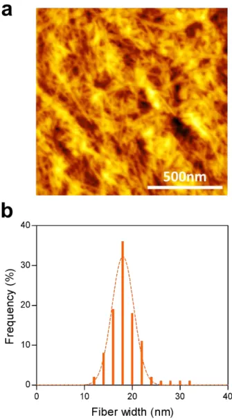
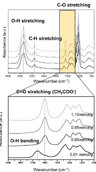
by the arrow is a fiber bundle in which nanofibrillization did not sufficiently occur. ... 47 Figure 10. (a) AFM image of CNF film with carboxylic content of 1.14 mmol/g. (b) The fiber width distribution of CNF with carboxylic content of 1.14 mmol/g measured by AFM... ... 48 Figure 11. FTIR spectra of CNF films according to carboxylic contents. The peak of carboxyl group is shown in detail from 1200 cm-1 to 1900
cm-1.... ... 50
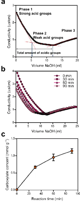
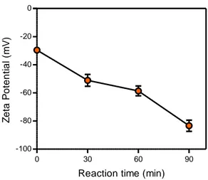
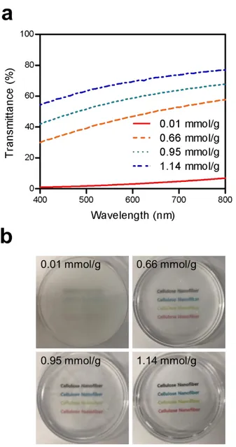
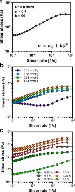
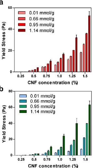
Figure 12. Transparency of CNF hydrogels. (a) Transmittance of CNF hydrogels according to the carboxylic contents at a wavelength from 400 to 800 nm. (b) Photographs of CNF hydrogels according to the carboxylic content at the CNF concentration of 0.75% ... 51 Figure 13. Shear stress of the CNF matrix as a function of shear rate. (a) Fitted shear stress-shear rate curve of the CNF matrix with the Herschel-Bulkley model at the carboxylic content of 1.14 mmol/g and concentration of 1.5 %. The shear stress-shear rate curves of the CNF matrix according to (b) the carboxylic content at the CNF concentration of 0.75 % and (b) the concentration at the carboxylic content of 1.14 mmol/g... ... 54 Figure 14. Elastic and viscous moduli of the CNF matrices according to (a) the carboxylic contents at the CNF concentration of 0.75 % and (b) the concentrations at the carboxylic content of 1.14 mmol/g. The yield stress is defined as the shear stress at the point away from the linear viscoelastic region... ... 56 Figure 15. (a) The yield stresses of CNF matrix measured by the shear stress-shear rate curve according to carboxylic content and concentration. (b) The yield stresses of CNF matrix measured by the shear elastic modulus according to carboxylic content and concentration.... ... 57
viii
Figure 16. Creep and recovery characteristics of CNF with the carboxylic content of 1.14 mmol/g and the concentration of 0.75 %. The shear rate is plotted for a constant applied stress, immediately after reducing the stress below the yielding threshold. ... 59 Figure 17. Optical and fluorescence microscopic images of printed cross-linked polyacrylic acid based model inks at various CNF matrix conditions according to carboxylic content and concentration... ... 62 Figure 18. Evaluation of printing fidelity of CNF matrix by sharpness of angled-line. (a) Schematic illustration for measurement of the difference (θd) between the ideal angle (θi) and the actual printed angle (θr). (b) Changes of θd at different CNF matrix conditions according to the carboxylic content and concentration. Optical and fluorescent microscopic images of the actual printed angle at CNF matrix condition of (c) 0.66 mmol/g with 0.5%, (d) 1.14 mmol/g with 0.75%, and (e) 1.14 mmol/g with 1.5%. (f) Color map of printing fidelity according to the difference of angle (θd) from 0° to 45°. ... 63 Figure 19. Analysis of sharpness according to the yield stress of the CNF matrix. (a) Printed shapes at the edged area when printing the angled line. (b) The variation of the printed angle according to the yield stress of the matrix and the yield stress of the ink. (c) Yield stresses of the CNF matrix and the cross-linked polyacrylic acid model ink... ... 64 Figure 20. Analysis of sharpness according to the injection pressure and printing speed at the CNF matrix concentration of 0.75% and carboxylic content of 1.14 mmol/g. (a) Changes of θd according to the different injection pressure depending on whether the injection pressure was fixed. Fluorescent microscopic images of the actual printed angle at the injection pressure of 20 psi with printing speed of 2 mm/s (b), the injection pressure of 50 psi with printing speed of 11.3 mm/s (c), the
ix
injection pressure of 20 psi with printing speed of 2 mm/s (d), and the injection pressure of 50 psi with printing speed of 2 mm/s (e). ... 65 Figure 21. Evaluation of printing fidelity by cross-sectional ratio. (a) Schematic illustration of the cross-sectional ratio analysis. (b) Changes in cross-sectional ratio at different CNF matrix conditions according to the carboxylic content and concentration. Optical and fluorescent microscopic images of the cross-section shapes of the printed lines at CNF matrix conditions of (c) 1.14 mmol/g with 0.75%, and (d) 1.14 mmol/g with 1.5%. (e) Color map of printing fidelity according to the cross-sectional ratio value from 1 to 2. ... 67 Figure 22. Schematic illustration of the crevasses formation condition according to the matrix yield stress. (a) Shape changes of printed ink cross-section due to the relationship between the CNF matrix yield stress and the hydrostatic pressure. (b) Hydrostatic pressure at the position where the nozzle passes through the CNF matrix.... ... 68 Figure 23. Optical and fluorescence microscopic images of linearly printed cross-linked polyacrylic acid based model inks at various CNF matrix conditions according to carboxylic contents and concentrations... 70 Figure 24. Evaluation of printing fidelity by the straightness of the line surface. (a) Schematic illustration of straightness analysis. (b) Changes in straightness at different CNF matrix conditions according to the carboxylic content and concentration. Optical and fluorescent microscopic images of the printed lines at CNF matrix conditions of (c) 0.01 mmol/g with 0.5%, (d) 1.14 mmol/g with 0.75%, and 1.14 mmol/g with 1.5%. (f) Straightness analysis with surface roughness of printed ink. (g) Color map of printing fidelity according to the straightness from 0 μm to 25 μm. ... 71 Figure 25. Color maps of printing fidelity. Printing fidelity according to (a) sharpness, (b) cross-sectional ratio, (c) straightness, and (d) total
x
averages. (e) Yield stress area of CNF matrix with high printing fidelity. The area indicated in light blue represents the region satisfying the relationship between the yield stress of the matrix and the hydrostatic pressure, and the area indicated in dark blue represents the region satisfying the relationship between the yield stress of the matrix and the yield stress of the ink.. ... 73 Figure 26. Optical and fluorescence microscopic images of printed petroleum-jelly inks at various CNF matrix conditions according to the carboxylic content and concentration.. ... 76 Figure 27. Optical and fluorescence microscopic images of linearly printed petroleum-jelly inks at various CNF matrix conditions according to the carboxylic content and concentration... ... 77 Figure 28. Evaluation of printing fidelity of CNF matrix with hydrophobic petroleum-jelly model ink. (a) Sharpness, (b) cross-sectional ratio, and (c) straightness evaluation by printing hydrophobic inks in various conditions of the CNF matrix. (d) Color map of printing fidelity of hydrophobic model ink in CNF matrix... ... 78 Figure 29. Creation of (a) triangular pyramid, (b) sphere, and (c) helix structures with petroleum-jelly ink. The ink contains green fluorescent microparticles for illumination. The structures were imaged from the side and the top. ... 79 Figure 30. Schematic illustration of printing fidelity in various CNF matrix conditions. (a) Three types of printed ink shapes at various CNF matrix conditions with low, appropriate, and high viscosity. Viscosity change due to the CNF entanglements at different (b) fiber dimension and (c) concentration. ... 81 Figure 31. Velocity flow fields within the CNF matrix of varying concentration using a nozzle (outer diameter = 0.3 mm) moving at 0.4 mm/s from right to left. Flow fields according to the concentrations of the
xi
CNF matrix at (a) 0.25%, (b) 0.5%, (c) 0.75%, (d) 1.0%, (e) 1.25%, (f) 1.5%... 84 Figure 32. Velocity flow fields within the CNF matrix materials of varying carboxylic content using a nozzle (outer diameter = 0.3 mm) moving at 0.4 mm/s from right to left. Flow fields according to the carboxylic contents of the CNF matrix at (a) 0.01 mmol/g, (b) 0.66 mmol/g, (c) 0.95 mmol/g, (d) 1.14 mmol/g.. ... 85 Figure 33. Effect of CNF concentrations and carboxylic contents on the velocity distribution in front of and behind the nozzle. Velocity magnitude profiles of the CNF matrix at different (a) carboxylic content and (b) concentration of the CNF matrix. ... 87 Figure 34. Matrix composition and printing path effects on the printing fidelity. (a) A schematic illustration of deformation occurred in already printed ink as the nozzle moves. (b) Three paths for evaluation of printing fidelity in multi printing lines at different CNF matrix concentration.... .. 89 Figure 35. Printing of the various inks in the CNF matrix. (a) Shear modulus of various types of ink. As hydrophilic ink, cross-linked polyacrylic acid ink and CNF ink were used, and as hydrophobic ink, petroleum-jelly ink and silicone ink were used. (b) Optical and fluorescent microscopic images of various inks printed in the CNF matrix with the carboxylic content of 1.14 mmol/g and the concentration of 0.75%... 91 Figure 36. Living cell printing inside the CNF matrix with the carboxylic content of 1.14 mmol/g and the concentration of 0.75%. ... 93 Figure 37. Printing of silicone elastomer-based soft actuator. (a) Optical image of the printed complex silicone elastomer structure inside the CNF matrix with the carboxylic content of 1.14 mmol/g and the concentration of 0.75%. (b) Feasibility test of 3D printed silicone elastomer-based actuator by the pneumatic or hydraulic pressure. ... 94
xii
Figure 38. Fabrication of a flexible microfluidic thin film with multilayered channels by matrix-assisted 3D printing in the CNF hydrogel. (a) Series of fabrication processes for three-layered continuous microfluidic channels designed by CAD. (b) Nozzle tip was moved to the three layers, and the petroleum-jelly-based removable ink was injected in the CNF hydrogel matrix. (c) It was possible to interconnect the layers by continuous injection of the ink in tip movement to the next layer. (d) CNF hydrogel matrix was dehydrated and formed a thin, compact microfluidic film. (e) Printed ink was liquefied at elevated temperature and removed under vacuum, forming an open-channel 3D microfluidic device. (f) Different shapes of channel patterns formed in CNF films... 96 Figure 39. Feasibility test of microfluidic channel devices. (a) Injection of two dye solutions to two separate channels. (b) Thickness of a CNF microfluidic device consisting of three-layered channels located vertically. Optical images of the junction area (c) and laminar flow in the CNF microfluidic channels (d). The channel surface was coated with silicone elastomer to prevent water absorption. The fibrous channel surface (e) was modified into a smooth surface (f), and the surface roughness changed significantly after coating (g) and was confirmed by AFM.. ... 98 Figure 40. Control of channel diameters by pressure applied to the 3D-printing ink. (a) as a function of applied pressure at a 3D-printing speed of 5 mm s–1 and (b) as a function of printing speed at an applied pressure of
25 psi using a 160 μm cylindrical stainless steel nozzle at 25 °C. (c) Channel size was controlled by simple adjustment of the applied pressure on the printed inks, which maintained their size after drying of the matrix... ... 100 Figure 41. Dimension control of the microfluidic device. (a) Processing map for determining the dimension of the microfluidic devices, denoting
xiii
regions resolved between the layers (filled-in squares) and unresolved between the layers (empty squares) as a function of the layer height between the nozzle tip and the applied pressure. (b) Two different dye solutions flowed through the devices at different layer height conditions. (c) Detailed image of the cross-sectional 3D microfluidic devices showing the two channels blocked by a cellulose barrier. (d) Variation of the maximum thickness of the device depending on the integration of the multilayered channels. (e) Photographs of six different solutions flowing in six-layered microfluidic devices without mixing... ... 102 Figure 42. pH sensing devices. (a) Design of the detection zone of a CNF microfluidic device. A universal pH indicator solution was dropped at the surface of the detection zone and dried until use. (b) Streams of DW, 1 M NaOH, and 1 M HCl were injected into the device sequentially. ... 104 Figure 43. Colorimetric analysis of heavy metal ions in a dual-mode. (a) Schematic drawing of the microfluidic device design for sensing heavy metal ions Ni2+ and Cr6+. UV-vis spectra obtained at different
concentrations of (b) potassium dichromate and (c) nickel nitrate hexahydrate for selective capture of heavy metal ions. (d) Calibration curves for the detection of Ni2+ and Cr6+ ions.... ... 106
Figure 44. Schematic illustration of the CNF-based cell culture platform embedding a microfluidic system. (a) 3D printing of Hphil-CNF in the matrix of Hphob-CNF hydrogel. (b) Matrix-assisted printing of petroleum jelly ink in the CNF hydrogels. (c) Dehydration of hydrogels for the formation of a condensed film microfluidic device. (d) Formation of channels in the Hphob-CNF and Hphil-CNF hydrogels in the process shown in (b). (e) Cell culture platform for selective diffusion of molecules from the flow... ... 109
xiv
Figure 45. (a) Photographs of matrix-assisted 3D printing of the Hphil-CNF ink in the Hphob-Hphil-CNF matrix. (b) Photographs of matrix-assisted 3D printing a petroleum jelly ink in an Hphob-CNF matrix... ... 110 Figure 46. Modification of Hphil-CNFs into Hphob-CNFs. (a) FT-IR spectra and (b) FE-SEM image of MTMS-CNF film. (c) The swelling ratio of CNF films according to MTMS reaction concentration. (d) Transparency of CNF films according to MTMS reaction concentration. (e) Photograph of a transparent Hphob-CNF Film modified with 1.0 % MTMS... ... 113 Figure 47. Selective diffusion of molecules in the platform. (a) Schematic illustration of the difference in diffusion tendency at the Hphil-CNF and Hphob-Hphil-CNF layers in the device. Time-lapse fluorescence microscopic images of 4kDa FITC-Dex flowing in the channel at the (b) Hphob-CNF layer and (c) Hphil-CNF layer. (d) Difference of diffusion tendency between Hphob-CNF and Hphil-CNF layered channels. (e) Change in fluorescence intensity according to distance from the channel surface and diffusion time. 4kDa FITC-Dex was used, and the intensity was measured according to distance from the CNF layered channel at intervals of 5 min. (f) Variation of diffusion tendency according to the size of FITC-Dex molecules... ... 115 Figure 48. Cell viability of the CNF-based open culture microfluidic platform. (a) A schematic diagram of cell culture with the platform embedding a single-channel structure. (b) Optical microscopic image of the platform cultured with fibroblast cells. Fluorescence images of live and dead assays of fibroblast cells cultured at the Hphob-CNF surface (c) and the Hphil-CNF surface (d). (e) Changes in relative metabolic activity of fibroblast cells in Hphob-CNF, Hphil-CNF, and tissue culture. Metabolic activity was measured with Alamar Blue assay after the cells were cultured for 1, 4, and 7 d... 117
xv
Figure 49. Effect of cisplatin on the viability of cells cultured at the surface of the platform. (a) A schematic diagram of a CNF-based microfluidic device for evaluation of cell proliferation rate of A549 cells. (b) Live/dead assay with A549 cells attached at the surface of the Hphob-CNF layer after 100 μM cisplatin solution was flowed in the channel. Live/dead assay with A549 cells attached at the surface of the Hphil-CNF layer after 0.01 μM (c) and 100 μM (d) cisplatin solutions flowed in the channel. (e) Change in the proliferation rate of A549 cells with a concentration of cisplatin solution in the channel. ... 120
1
Ⅰ. Introduction
The current major problems in 3D printing are focused on inks and printing systems. However, in addition to ink, the matrix is one of the most critical components in 3D printing of soft matter. Nevertheless, matrix research is rarely reported due to the lack of selectable materials. The matrix plays an important role in maintaining printed structures in a free-standing form in the bulk space [1, 2]. To this end, the simple removal of ink from the matrix enabled the construction of microchannels to become the starting point of the research on matrix-assisted 3D printing of microfluidic devices. In addition, the deformation of a bulky matrix into a film enforced the vertical integration of 3D structures by natural dehydration and it made the research more challenging.
Matrix-assisted 3D printing (MAP) using a matrix and ink was most effective for printing free-standing structures and a smart choice for the rapid prototyping of microfluidic systems due to the ease of processing and freedom of design. The free-standing 3D structures could be fabricated by extruding inks in the liquid matrix including PDMS prepolymers [3, 4], self-healing hydrogels [5] and granular gel media [6]. A green material, cellulose nanofiber (CNF) hydrogel, was adopted as a potential novel matrix in the research, and the critical factors were investigated for the 3D printing of free-standing structures using this material.
Cellulose is a limitless resource on earth, and CNF has been widely researched from a new angle in recent decades. Due to a high water content of 98% and superior mechanical properties [7, 8], CNFs have been applied as substrates of transparent films [9-12], porous packaging [13], tissue engineering scaffolds [14-16], hydrogels and aerogels [17-19], and battery electrodes [20-22]. In recent years, CNFs has been used as an additive to ink for the enhancement of low viscosity in the ink and the directional
2
deformation of structures, and as an embedding material for direct 3D printing [23-26]. However, no research has been reported on the use of CNFs as a matrix in 3D printing or a platform for microfluidic devices. Therefore, the quantitative criteria needed to be suggested for excellent printing fidelity.
Here, the rheological properties of the CNF matrix were adjusted by controlling the carboxylic content and concentration. The carboxylic content was changed to control the fiber dimension during the nanofibrilation process. The rheological properties of CNF were varied with the concentration of CNF between 0.25 and 1.5%. The printing fidelity was evaluated by observing the features of printed inks inside the CNF matrix at the controlled conditions. The controlled rheological parameter was strongly related to the accurate printing of 3D structures. It was possible to print microfluidic channels using a CNF hydrogel matrix in a simple and rapid process. The vertical integration of the microchannels printed in 3D was achieved through simple drying. This is a unique new concept in the fabrication of microfluidic systems that have not yet been reported. The bulky CNF hydrogel matrix deformed into a thin film during drying. Since a thin and dense barrier of CNF was formed between the printed features, the resolved integration of microchannels was naturally achieved.
CNF hydrogels are composed of high aspect-ratio natural nanofibers; CNF films with microchannels are flexible and even foldable after dehydration, and additional selective finishing processes were available. In addition, it was possible to monitor the chemical reactions in the microchannels due to the high transparency of CNF-based devices fabricated by matrix-assisted 3D printing. Another unique feature of our microfluidic devices is that they are distinct from paper wicking sensing platforms, which suffer from undesirable retention, high adsorption of analytes to the bulk and the opacity of paper [27-30].
3
This is the first report to fabricate microfluidic channels in the CNF matrix using 3D printing and to integrate the 3D structures by deforming the matrix to 2D. It will be applicable to the compact design of microfluidic devices and the effective stacking of multitasking devices by simply connecting the layers. With a simple process and easy control of composition, CNF hydrogel could be used as a generic matrix for 3D printing with a combination of a variety of ink materials in the future.
4
Ⅱ. Literature survey
2.1. Various 3D printing technologies.Charles W. Hull first conceived the earliest 3D printing technology in 1986 under the name of “stereolithography” [31]. Stereolithography is a method in which thin layers are sequentially printed by applying ultraviolet rays to a resin that can be cured to produce a three-dimensional structure [32-34]. This advancement in three-dimensional printing has enabled a new dimension of printing over the last few decades. The production of 3D structures enabled us to fabricate prototypes, especially in the industry, and specialized in the production of personalized and customized products [34-36]. In addition to manufacturing these products, 3D printing has been used in a variety of fields such as medicine, science, and education. By using 3D printing, doctors can create patient-customized organ structures, and labs use them to create customized scientific tools.
3D printing technology has evolved in many different ways, but they share the same principles. It is to make three-dimensional structures from one-dimensional lines and two-one-dimensional faces by stacking them. Those multiple steps make 3D printing slower to fabricate 3D structures compared to a conventional molding method. However, 3D printing has strength in manufacturing various topologies that are limited using a mold. To get a final product with a 3D printer, several steps have to be passed. First of all, a structure should be designed with a computer and then it should be sent to a slicer that breaks it up into one or two-dimensional structures depending on the 3D printing technology. The disassembled structures are input to the 3D printer, and printing will start. Various three-dimensional structures can be produced directly from various materials with 3D printing technology. Common light- and ink-based 3D printing methods are described in Figure 1.
5
Stereolithography, abbreviated as SLA, was the first 3D printing technique. SLA is a laser-based printing technology. In SLA, the liquid resin is selectively photopolymerized by a rastering laser. When one layer is printed, a new layer of liquid resin is introduced, and the laser is continuously imaged and cross-linked. This process is repeated until the desired 3D structure is completed. State-of-the-art methods, including Digital Projection Lithography (DLP) [37-40], Continuous Liquid Interface Production (CLIP) [41, 42], and Two-Photon Polymerization (2PP) [43-45], are all based on these basic concepts. DLP and CLIP technology, however, differ from conventional SLA technology in that they do not start in one-dimensional lines but in two-dimensional faces using micromirror array device.
In Selective Laser Sintering (SLS), the polymer particles in the powder bed are locally heated and fused by a rastering laser [46-49]. The layer is printed, and fresh powder spreads over the printed layer and locally sintered. Spherical powders with a diameter of 10 μm to 100 μm are generally used for uniform dispersion of the powder. Unsintered particles in the powder bed support the structure during the manufacturing of the three-dimensional structure [50]. Besides, the unsintered powder is recycled after the 3D printing is completed and removed from the powder bed.
Fused Deposition Modeling (FDM), the most commonly used method, is a cost-effective and straightforward approach that utilizes the melting and solidification of materials [51-54]. The polymer is melted and laminated by the heat applied at the nozzle end. The basis of FDM technology is the manufacture of filaments by extrusion process. In general, thermoplastic polymers are widely used, such as polylactic acid (PLA) [55-57], polycaprolactone (PCL) [58, 59], ethylene-vinyl acetate (EVA) [60, 61], and acrylonitrile butadiene styrene (ABS) [52, 62, 63]. To 3D print a stable three-dimensional structure with high resolution, it is necessary to understand the properties of the material thoroughly.
6
The Direct Ink Writing (DIW) method, designed to print soft materials such as hydrogels and silicones, is very similar to FDM, which produces 3D structures by ejecting ink from nozzles [64-69]. However, DIW deals with soft materials without using thermoplastic polymers. Therefore, the characteristics of the materials are different from those of the FDM method. Appropriate rheological and shear thinning properties are required to eject and stack ink [70-74]. In most cases, the hydrogel is loaded into the syringe and discharged from the nozzle by hydraulic, pneumatic, or screw pressure applied to the syringe. As the shear stress applied at the nozzle, the inks exhibiting shear thinning characteristics will flow well due to their low viscosity at a high shear rate. When the shear stress disappears as ink is ejected, the viscosity will increase to maintain its shape. Therefore, the rheological properties of ink materials are critical for excellent printability [75]. Many researchers have focused on controlling the rheological properties and have outlined the critical elements for stable printing. To be applied to DIW, the ink must be gelled quickly and easily, and it must be well fluidized at the nozzle and ejected with a small resistance. After dispensing, the ink must have a high zero shear viscosity to have sufficient strength to maintain the printed structure. Besides, the structure must be easily cured by ions, heat, or ultraviolet light.
Hydrogel is a material that traps a large amount of water, so it shows very similar physical properties to human organs [76-79]. Many researchers have been working on the use of hydrogels in the biomedical field, which further expands the utility of DIW. 3D bio-printing is a technique for producing three-dimensional structures by mixing living cells with a hydrogel ink to produce living structures having biological and mechanical properties suitable for clinical restoration of tissue and organ functions [80-82].
7
Figure 1. Common and ink-based 3D printing methods. (a) The light-based 3D printing method known as continuous liquid interface production. (b) Light-based selective laser sintering of powders. (c) Light- and ink-based photocurable inkjet printing of photopolymerizable resins. (d) Ink-based fused deposition modeling of thermoplastic filaments. (e) Direct ink writing using viscoelastic inks [83].
8
2.2. Matrix-assisted 3D printing (MAP).
Soft materials such as hydrogels or silicones are very vulnerable to deformation after 3D printing with the DIW method, which limits designs and topologies. For example, when printing the bridged structure, it can easily collapse if there is no proper support. Recently, a method for overcoming the limitations of the DIW method has emerged. A technique called embedded 3D (EMB3D) printing or matrix-assisted 3D printing (MAP), which involves direct patterning of inks within soft supporting matrices along predefined omnidirectional printing path (Figure 2) [70, 84]. Since the soft material is printed inside the supporting matrix, the ink cannot easily be deformed. To date, these technologies have been used in a wide variety of applications, such as manufacturing 3D microvascular networks inside hydrogels or manufacturing soft robots, soft sensors, microfluidic systems, and scaffolds [1, 82, 85-87].
9
10
2.2.1. Rheological requirements for MAP.
In the early days, three components were essential for the printing concept of MAP. It consisted of matrices with two different rheological properties and single ink [1, 87]. When the ink was printed inside the matrix showing high storage modulus, crevasse was generated along the path of the nozzles. Another matrix having low viscosity was poured on the existing matrix to fill the crevasse. Thus, a multi-component material system had been developed that consists of ink, a matrix with high storage modulus, and a flowable filler matrix. These components were adjusted to exhibit the appropriate rheological properties needed to maintain high printing stability throughout the 3D printing and curing process. Besides, it had the characteristic of being chemically compatible between matrices showing two different rheological properties. Several criteria must be fulfilled when designing a support matrix and filler matrix for MAP. First, the matrix should facilitate the patterning of the desired ink filament without breakage. Second, as the nozzles pass through the matrix, any defects that occur during printing must be quickly healed by the highly fluid matrix.
As technology advances, instead of using multi-matrices, matrix materials began to emerge that allowed self-healing by adequately adjusting the rheological properties with a single matrix [70]. This development had made it possible to print the three-dimensional structures within the matrix through MAP. To secure higher printing stability in the single matrix-based MAP, many researchers have reported appropriate conditions by controlling the rheological properties of the matrix and the ink materials. Ink and matrix materials must meet several requirements to enable MAP. The ink must show shear-thinning property where the viscosity decreases as the shear rate is applied to ensure stable passage through the nozzle [70]. Qualitatively, the ink must have yield stress, and the matrix material must exhibit shear-thinning and yield stress properties as well as the ink. If the shear modulus (G') of ink
11
is too large for the shear modulus of the matrix, the nozzle can pull the ink in the matrix material. In contrast, if the G' ink is too low compared to the G' matrix, the ink filaments may fragment within the matrix. The matrix must have a yield stress low enough that the nozzle can move freely throughout the matrix. Moreover, the crevasse formed as the nozzles pass should be filled up quickly. However, if the yield stress of the matrix is too low compared to the viscous stress associated with nozzle displacement, the nozzle will create a stress field that deforms the printed structure. If the yield stress of the matrix is too large, a gap is formed behind the nozzle, requiring the introduction of filler fluid to the top surface of the matrix. Thus, to be utilized as matrix material, the matrix must exhibit time-dependent rheological behavior due to dynamic reconstruction at the microscale, and the crevasse of nozzle movement has to be recovered quickly. Besides, the ink and matrix materials must be chemically compatible and exhibit the desired composition and functionality required for the application.
2.2.2. Various matrix systems for MAP.
Unlike the DIW method, MAP always requires a pair of materials, ink, and matrix. Various ink and matrix materials have been reported for various applications and purposes. The various matrix systems are presented in Figure 3.
The first matrix material is the Pluronic F127, a triblock copolymer with a hydrophobic poly (propylene oxide) (PPO) segment and two hydrophilic poly (ethylene oxide) (PEO) segments arranged in a PEO-PPO-PEO configuration [1, 82]. Aqueous Pluronic F127 solutions undergo a phase transition that is both concentration and temperature-dependent. Under ambient conditions, the PEO-PPO-PEO species form micelles that consist of a PPO core surrounded by a PEO corona above a critical micelle concentration (CMC) yielding a physical gel, as reflected by the substantial increase in shear elastic
12
modulus, G' as the concentration exceeds the CMC. Besides, these Pluronic F127 solutions also possess a critical micelle temperature (CMT) [88-90]. Above the CMT, the PPO block dehydrates leading to pronounced hydrophobic interactions that drive micelle formation. However, below the CMT, the hydrophobic PPO units are hydrated, allowing individual PEO-PPO-PEO species to become soluble in water, thereby inducing a sol-gel transition for systems whose concentration resides above the CMC. This particular rheological property has led many researchers to use Pluronic F127 as a 3D printing matrix.
To mimic the 3D microvascular networks, a fugitive ink, fluid filler matrix, and gel matrix, whose properties were tailored for printing and subsequent transformation into the desired structures were developed. 3D biomimetic microvascular networks composed of a hierarchical 3D branching topology with microchannel diameters ranging from 200–600 μm could be constructed using this system [1]. Embedded vasculatures could also be prepared by patterning bio-inks containing cells inside the Pluronic F127 matrix [82].
Recently, matrices made by adjusting rheological properties such that self-healing property for self-healing the crevasses formed by moving nozzles have been reported [70]. This technique includes the printing of shear-thinning hydrogel “inks” directly into self-healing “support” hydrogels. The MAP was possible because of their noncovalent and reversible bonds that could be disrupted by the application of a physical stimulus such as shear stress, and that reformed rapidly upon removal of the stimulus. Such properties permitted their use as injectable hydrogels, and consequently, as inks in extrusion-based 3DP. These same properties enabled the use of a guest–host hydrogel as a support matrix, which deformed to accommodate extruded material and self-heals to maintain material localization.
A study has been reported to produce a matrix using gelatin, which is a biocompatible protein material [91]. The additive manufacturing of complex
13
three-dimensional (3D) biological structures using soft protein and polysaccharide hydrogels were challenging to create using traditional fabrication approaches. These structures were built by embedding the printed hydrogel inks in a hydrogel matrices that serves as a temporary, thermoreversible, and biocompatible support.
Besides, a cross-linked acrylic acid-based matrix has been reported [84]. This material, called Carbopol, has the form of a granular gel and is considered to be the best matrix material to date. Gels made from soft microscale particles smoothly transition between the fluid and solid states, making them an ideal matrix in which to create macroscopic structures with microscopic precision. While tracing out spatial paths with an injection tip, the granular gel fluidizes at the point of injection and then rapidly solidifies, trapping injected material in place. This physical approach to creating three-dimensional (3D) structures negates the effects of surface tension, gravity, and particle diffusion, allowing a limitless breadth of materials to be written. With this method, silicones, hydrogels, colloids, and living cells were used to create complex large aspect ratio 3D objects, thin closed shells, and hierarchically branched tubular networks.
Numerous researchers have sought to fabricate the final product into devices, not just 3D printing. The most suitable material for this purpose was silicone. Silicone is a soft material with elasticity through the hardening process and has been applied in various applications such as microfluidics, sensors, actuators, and soft electronics [92-94]. A study has been reported in which ink consisting of carbon black particles was printed on silicone oil to produce a three-dimensional strain sensor [87]. Conductive carbon grease displayed the rheological properties required for 3D printing.
Silicon matrix has also been reported for its application in soft robotics as well as strain sensors [86]. The Pluronic F127 hydrogel, which can be easily removed to form a channel in the silicon matrix, was printed. And the catalyst
14
was prepared in a hydrogel form that would act as a power source. Two hydrogel-based inks were printed within the molded matrix materials. These printed features were interfaced with each other as well as with the soft controller through the use of ‘fugitive plugs’ introduced at the inlets of the controller before filling the mold with the matrix materials. The catalytic ink contains platinum particles suspended in a mixture of Pluronic F127-diacrylate and poly (ethylene glycol) F127-diacrylate that is photo cross-linked after printing.
A granular organic microgel system was used as an oil-based 3D printing support matrix [95]. The organogel particles were formed through the self-assembly of diblock and triblock copolymers dispersed at low concentration in mineral oil, in contrast to traditional polymerization routes to synthesizing microgels. 3D printing was performed by translating an injection needle through the organogel medium while depositing features made from numerous silicone-based materials. Silicone features as small as 80 mm could be printed and remain indefinitely stable without cross-linking. The breakup of unstable features could be delayed markedly by increasing the viscosity of silicone inks, allowing even higher-precision (30 mm) structures to be manufactured.
15
Figure 3. Various matrix systems for MAP. (a) Fluorescent image of a 3D microvascular network fabricated via omnidirectional printing of a fugitive ink within a photopolymerized Pluronic F127-diacrylate matrix [1]. (b) Confocal images of a filament of a fluorescein-labeled ink and then a continuous spiral of a second, rhodamine-labeled ink printed into a self-healing hydrogel matrix [70]. (c) A dark-field image of the arterial tree mounted in a perfusion fixture to position a syringe in the root of the tree [91]. (d) A thin-shell model octopus is made from multiple connected hydrogel parts in a cross-linked acrylic acid matrix [84]. (e) Optical image of matrix-assisted 3D printed architectures, including a body-centered cubic lattice [96]. (f) Macroscopic image of a perfusable network of hollow vessels being 3D-printed into the micro-organogel matrix material [95].
16
2.3. Cellulose.
Cellulose is one of the most abundant natural macromolecular organic compounds on the planet and is produced by billions of tons every year as long as solar energy is present [97]. Therefore, many researchers actively developed the technology to utilize the cellulose component of the plant as a resource of energy, chemicals, or food for the future. Recently, the importance of cellulose to resource and environmental issues is increasing. Cellulose-based wood has long been used in energy sources, apparel, housing, ships, and many other fields. In conclusion, the study of cellulose resources is the most important field to meet the human desire for new materials and new energy.
Cellulose is a carbohydrate polymer composed of 44.4% carbon, 6.2% hydrogen, and 49.4% oxygen [98]. It is a linear polymer composed of the monosaccharide glucose, β-D glucose. Cellulose is a condensation polymer in which β-D glucose is connected as the hydroxyl group attached to C1 of one glucose molecule and the hydroxyl group attached to another C4. The link between molecular units is called 1, 4-D-glucosidic bond or β-glucosidic oxygen bridge. Multiple condensation reactions result in linear polymer chains that are very long and do not have side branches. The degree of polymerization, representing the length of the polymer chain, can reach up to 10,000 anhydroglucose units. The molecular formula of the anhydroglucose unit, which is a repeating unit, is C6H10O5; thus, the
molecular formula of cellulose can be specified as (C6H10O5)n [99]. Cellulose
is obtained from various sources such as cotton and wood, but the chemical structure is the same. There is only a difference in content and degree of polymerization, molecular weight. Cotton, for example, contains more than 95% of cellulose and about 50% to 60% of wood [98, 100].
Cellulose is a linear polymer, but its structure is very complicated due to the strong intermolecular bonds between cellulose molecular chains.
17
Cellulose generates strong hydrogen bonds between the chains due to the many hydroxyl groups. This hydrogen bond is enhanced by successive alternating steric arrangements of anhydroglucose units. Thus, cellulose is highly crystalline, regardless of its source. The region with very high crystallinity is the region where hydrogen bonds are maximized, and the cellulose molecules parallel to each other are tightly arranged. Cellulose does not dissolve in some chemicals because the crystalline regions are difficult for chemicals to penetrate. Ramie, cotton, and flax contain 60-87% crystalline cellulose, while wood is 50-65%.
2.3.1. Cellulose nanofiber (CNF).
Cellulose particles that are more than one dimensional on the nanoscale (1-100 nm) are called nanocelluloses. Different terms in various cellulose nanotechnology and various technical committees and organizations (ISO TC 6 and TC 229; TAPPI and CSA Z5100-14) have been reported, such as nanofibrillated cellulose (NFC), microfibrillated cellulose (MFC) or cellulose nanofibers. Although the work of standardizing this has not yet been completed, most experts use the term “cellulose nanofibrils” for nanocellulose.
Bacterial cellulose (BC) and electrospun cellulose nanofibers (ECNF) are also considered nanocelluloses. Cellulose nanocrystal (CNC) and cellulose nanofibrils (CNF), however, are much more common because they are produced by breaking down cellulose fibers into nanoparticles (a top-down process). On the other hand, BC and ECNF are produced by the accumulation of nanofibers (a bottom-up process) from small molecules, which makes the mass production of BC and ECNF still in doubt. Regardless of the type of nano cellulose, it shows hydrophilicity, relatively large specific surface area, and enormous potential for surface chemical modification.
18
2.3.2. Extraction methods of CNF.
Cellulose is present with hemicellulose and lignin in trees or plants. The latter is generally removed before manufacturing CNF by various cooking and bleaching methods similar to those used in the paper industry. The CNF production method generally involves several operations: purification, enzymatic hydrolysis, repurification, and final homogenization. Therefore, the CNFs with different characteristics could be produced depending on the production process. The CNFs produced by these various methods show different morphological characteristics. In particular, nanofiber dimensions and the amount of residual fine fiber fragments, surface chemistry, crystallinity, and DP are different.
Dry cellulose pulp can be broken down into small pieces using mechanical methods. However, it usually leads to fiber breakage instead of fibril exfoliation. As a result, CNFs with a low degree of polymerization, low crystallinity, and low aspect ratio are produced. So the mechanical properties of subsequent nanomaterials are relatively weak. The energy must be exceeded over the hydrogen bond between the fibers to exfoliate rather than cut the nanofibers. For this reason, CNF is generally produced in aqueous media, which loosens hydrogen bonds between fibers. In general, cellulose is dispersed at low concentrations (<5%) due to its high water absorption, creating a high viscosity suspension. Refining, homogenization, and grinding are the most common techniques used to produce CNF. These techniques are most efficient for exfoliation of fiber cell walls and CNF separations and are suitable for upscaling. Therefore, it is currently used for the industrial pilot production of CNF.
Producing CNF using only mechanical decomposition requires high energy and cost [101, 102]. Since the beginning of the CNF research, intensive research has been carried out to improve the degree of nanofibrillation and reduce energy demand. Recent methods of CNF production include various
19
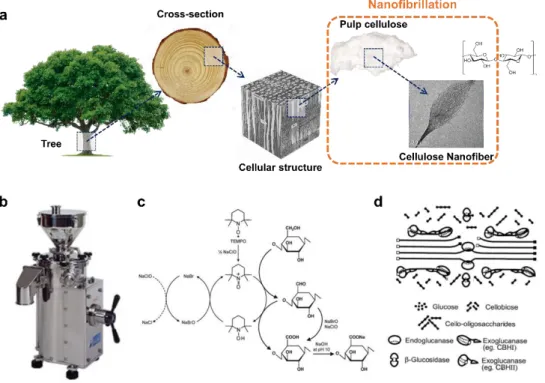
biological and chemical pretreatments. This type of pretreatment has a significant impact on the CNF output. The top-down process for cellulose nanofiber extraction is described in Figure 4.
Some enzymes are known to promote hydrolysis of cellulose and to enhance nanofibrillation. Cellulase was used to improve cellulose fibrillation in the papermaking process [103]. Since then, extensive research has been carried out, from mild enzymatic hydrolysis to facilitate the purification process, to strong hydrolysis to convert cellulose to glucose for further production of bioethanol. Recently, the production of CNF with mild enzyme hydrolysis has been reported [104, 105]. In these studies, the single component endoglucanase, Novozym 476 was used as the enzyme.
The introduction of negatively charged (carboxyl or carboxymethyl) groups on the fibers is known to improve the exfoliation efficiency of nanofibrils. This is caused by the electrostatic repulsion between negatively charged cellulose nanofibrils [106, 107]. Based on the same principle, sulfurous acid pulp is known to be easier to peel than conventional kraft pulp. 2,2,6,6-tetramethylpiperidine-N-oxyl (TEMPO) was reported for improving nanofibrillation since 1993 [108]. TEMPO is radical for the selective oxidation of monosaccharide primary alcohol groups, and this process has become one of the most popular topics in the field of selective oxidation of cellulose.
Carboxymethylation is another way for cellulose pretreatment. Carboxymethyl cellulose was first manufactured in 1918 and already commercially produced in Germany in the early 1920s [109]. The production of CNF from carboxymethylated cellulose as a new type of material was described. Carboxymethylated cellulose fibers were prepared by chemical pretreatment to remove unfibrillated fibers by high-pressure homogenization, sonication, and centrifugation. Nanofibrillated cellulose had a cylindrical cross-section of 5-15 nm in diameter and up to 1 µm in length.
20
Figure 4. Top-down process for cellulose nanofiber extraction. (a) Hierarchical structure of wood: from tree to cellulose, (b) Image of mechanical grinder, (c) Regioselective oxidation of C6 primary hydroxyls of cellulose to C6 carboxylate groups by TEMPO/NaBr/NaClO oxidation in water at pH 10–11 [12]. (d) The enzymatic hydrolysis model of cellulose.
21
2.3.3. Rheological properties of CNF.
The rheological properties are critical for the design and operation of some processes such as pumping, mixing, storage, and extrusion. Therefore, understanding how to control the rheological behavior of CNF suspensions is essential to utilize the functionality of the material. Besides, the mechanisms controlling the rheological properties of CNF suspensions could be applied to other nanofiber types of suspensions.
CNF suspension has gel-like behavior at concentrations of 1.0% and has very complex rheological properties [105, 110]. CNF suspensions exhibit both pseudoplastic and thixotropic properties [111, 112]. Flowing the CNF suspension requires deformation of the individual flocs and deformation of the three-dimensional fiber network. Regardless of the production conditions, all types of CNF suspensions decrease in viscosity with increasing shear rate showing shear-thinning properties. CNF has a thixotropic property, that is, a viscosity decreases when a stable shear rate is applied, and when the shear rate decreases to zero, the viscosity rises again to the same level. Therefore, time dependence is significant, so it is essential to measure steady-state flows. Viscosity and shear stress increase as a function of CNF concentration. As mentioned above, these suspensions have shear-thinning behavior, which is observed at a wide range of shear rates. In many studies, the Newtonian plateau was reported between low and high shear rate regions, and hysteresis loops were observed when increasing and decreasing shear rates. It is noteworthy that the Newtonian plateau and hysteresis were both observed with or without chemical pretreatment. These were associated with the formation and destruction of shear-induced structures in CNF suspensions.
CNF suspensions form a network structure with a low solids content. Oscillatory shear measurements are typically performed to study the linear viscoelastic properties of these structures. Oscillatory strain sweeps are performed to determine the strain domain where the linear strain viscoelastic
22
regions, the storage (G') and loss (G") modulus, are independent of the strain. The oscillatory frequency measurements are performed on strains in the linear viscoelastic region. An example of linear viscoelasticity measurements for TEMPO-oxidized CNF suspensions at various concentrations (0.5-1.5 wt%) is reported [113]. After exceeding the critical strain (about 1%), the elastic CNF network is destroyed, which is reflected by the nonlinear behavior of the dynamic modulus. The CNF suspension forms a gel even at low concentrations. This is confirmed by G'> G", where G' and G" are parallel to each other and mainly frequency independent. These gel-like properties have been reported for CNF suspensions at low concentrations of 0.125% corresponding to the gel point, after which the nanofibrils begin to form interconnected networks. As the concentration of CNF increases, a stronger fibrous network is formed, which increases the dynamic modulus widely reported in other studies [111, 114-116].
23
2.4. CNF as a 3D printing material.
Cellulosic materials without chemical modifications are generally considered unsuitable for extrusion or sintering based 3D printing because cellulose decomposes on heating before it melts and fluidizes. On the other hand, CNF hydrogel exhibiting shear-thinning behavior can be considered as an ink material for 3D printing. The rheological properties of CNF already mentioned are considered to be very suitable for use as 3D printing inks [57, 117-121]. A new era is coming with 3D printing using cellulose materials to replace synthetic plastic materials (Figure 5).
2.4.1. CNF as a rheology modifier.
Inks properties are of critical importance in 3D printing [122]. In particular, 3D printing inks require a well-controlled viscoelastic response (high viscosity and shear-thinning behavior) [122-127]. The shear-thinning properties of polymer solutions were often used to achieve this result. CNF has been used as the viscosity modifier in a wide range of industrial products for many years. The cellulose chains can form hydrogen bonds between each other, restricting the water motion and further increasing the viscosity. However, when an external force is added, the mixing energy will break the hydrogen bonds between cellulose chains, and subsequently, the chains will be aligned in the direction of flow, leading to decreased viscosity through shear-thinning or pseudoplastic behavior [128]. The rheological properties of CNF, therefore, provide the desired low viscosity at high shear rates, while providing high viscosity as the high shear rates are stopped. The thixotropic property of CNF makes them reasonable 3D printing inks.
CNF in hydrogel stands out as a biomaterial in bio-ink due to its low cytotoxicity and structural similarity with ECM. CNF was first proposed to manufacture scaffolds for application by tissue engineering using inkjet printing techniques [126]. Carboxymethylated nanocellulose also
24
successfully printed on a TEMPO-mediated oxidized nanocellulose film [129]. In order to improve the printing stability of the ink, the CNF hydrogel can be formulated with auxiliary materials, which can be mixed with CNF to control the rheological properties of the ink. Besides, as the CNF addition amount increased, it was possible to secure structural stability when forming the three-dimensional structure of the ink. As ink modifiers, water-soluble lignosulfonate (LS) could also be added to the 2% CNF obtained through enzymatic hydrolysis to control the rheological properties. Ionically cross-linked alginates can be formulated by combining the concentration of 2.5% CNF and alginate obtained through mechanical treatment and enzymatic hydrolysis when shape fidelity was improved [121, 126, 130].
As a result of tremendous interest in natural cellulose-based bio-inks, it is commercialized under the trademark CELLINK by CELLINK AB (Sweden). CELLINK can be prepared from 2% plant-derived CNF and 0.5% alginate. Using CELLINK, the structure of the ear with pores and cartilage cells with high shape fidelity can be produced. Various studies have been made to manufacture bio-inks by compounding photocurable polymers with CNF. Representatively methacrylated gelatin (GelMA) was used with CNF hydrogels as a photocrosslinkable material naturally derived from collagen with properties to improve biological interactions [119].
2.4.2. CNF as a reinforcement.
CNF has been studied as a novel nanofiller to reinforce materials [131-133]. Many researchers carried out a biomimetic 3D printing study using wood-derived CNF as a stiff filler [134]. The composite architectures were printed with a hydrogel composite ink containing stiff CNF that had been embedded in a soft acrylamide matrix mimicking the composition of plant cell walls. The CNF underwent shear-induced alignment as the ink flowed through the deposition nozzle during printing, producing printed filaments with
25
anisotropic stiffness, and hence, swelling behavior in the longitudinal direction (defined by the printing path). CNF alignment was directly observed in the printed samples compared to isotropic cast sheets of the same material. CNF was adopted to improve the mechanical performance of polylactic acid (PLA) in 3D printing [135, 136]. The incorporation of PLA-g-CNFs improved the storage modulus of the composite filaments both below and above the glass transition temperature, which could be due to the increased crystallinity of the PLA matrix.
3D printing of polypropylene (PP) is difficult, due to not only the high temperatures required for PP to be printed but also due to shrinkage and warping during the printing process. To overcome the shrinkage and warping problem, CNF was incorporated into PP because CNF has a low thermal expansion coefficient of 0.1 ppm/k [137]. The composites were prepared through mixing CNF and PP pellets in a twin-screw co-rotating extruder. Rheological tests showed that the elastic modulus, complex viscosity, viscosity, and transient flow shear stress of PP were all increased with the addition of 10 wt% CNF, while the creep strain of PP was reduced. Flexural strength and modulus of PP were also improved by adding CNF.
26
Figure 5. Cellulose as a 3D printing material. (a) 3D printed specimens of wood flour/PLA composites for tensile properties measurement [138]. (b) 3D printed cellulose acetate-based miniature eyeglass frames [139]. (c) 3D printed cellulose nanocrystal grids [117]. (d) Simple flowers composed of 90◦/0◦ bilayers oriented with respect to the long axis of each petal, with
time-lapse sequences of the flowers during the swelling process [134]. (e) A small chair is printed with CNF and freeze-dried [140]. (f) 3D printed octopus structure from 2.8 % T-CNF gel [120]. (g) Top view of 3D-printed “letters” after cross-linking and freeze-drying of CNF [141]. (h) 3D printed human ear with CNF/alginate bio-ink [126]. (i) 3D printed human nose structure with CNF/GelMA bio-ink [119].
27
2.5. CNF based devices.
CNF stabilized by hydrogen bonds that form highly crystalline domains. Thus, cellulose nanofibers have a CTE of 0.1 ppm/K, lower than quartz and glass, and estimated strength of 2-3 GPa, 5 times stronger than mild steel. Nanofibers also show excellent heat transfer properties comparable to glass. Optically transparent TEMPO-oxidized CNF nanopaper can be used as an alternative to traditional substrates (glass, plastic, and plain paper) in a variety of applications such as smart sensors, flexible energy storage, wearable electronics, and optoelectronic devices (Figure 6) [9, 142-150].
2.5.1. Transparent and thin device through dehydration.
Aqueous dispersed CNF can be obtained in a system that is disintegrated in water during CNF manufacturing. CNF aqueous dispersion can be actively utilized due to its unique rheological property, as mentioned above. However, if CNF film is manufactured through dehydration and drying, CNF thin films with unique properties can be obtained. An essential property of CNF is that light scattering can be suppressed [9, 142]. If the nanofibers are densely packed, and the gaps between the fibers are small enough to avoid light scattering, the cellulose material can maintain a high level of transparency.
The optical haze and transmittance of the transparent paper can be adjusted by the porosity and size of the fiber [151-153]. It is important to design transparencies with adjustable optical properties in an inexpensive process. Recently, cellulose was used to investigate very transparent paper. Plain wood fibers act as a scaffold for paper, while CNF fills voids to reduce light scattering. Since CNF has an optical index of refraction 1.5 that is similar to regular fibers in contrast to air, the paper can be adjusted from opaque to transparent, depending on the amount of space filled with CNF. Hybrid paper has the same transmittance of 91.5% as PET when the CNF concentration of the paper reaches 60%. The haze of hybrid paper is much higher than that of