1. INTRODUCTION
Until now, many types of grid connected power systems (GCPS), which have different kinds of power resources such as photovoltaic array, wind turbines and fuel-cells have been demonstrated and developed. Some of these power units can be directly connected to the grid networks, however, most of them have power electronics basedinterfaces. For example, photovoltaic array require DC to AC conversion, and wind turbine require AC to DC and DC to AC converter systems. GCPS, in general, consist of inverter module, LC filter, isolating transformer and grid network part. The inverter module is a power generator and has switchingsemiconductors, and LC filter is a passive component for filtering out switching frequency band noise. Isolating transformer eliminating zero sequence (or DC components) in the generated voltage is also necessary for protection.
In GCPS, low line current distortion and high power factor in phase with the grid voltage are desired control objectives including high switching frequency inverter with shorter computation time. Among the components of grid connected power systems, inverter module is a core part, and recently, there has been researched on inverter control method to solve the fundamental problems on grid-connected systems of poor output power quality. Actually, switching frequencycomponents and pre-exiting grid voltage disturbances mainly degrade the output power quality.
Switching frequency components can be eliminated with a well designed LC filter considering isolating transformer, however, clearing out pre-exiting grid voltage disturbances needs another control solution. In this paper, a robust control scheme using neural networks is presented for the inverter to generate high quality balanced 3-phase currents and to control power at the output of the inverter
. The usefulness of the proposed method is shown with some
simulation results.
2.Control system description
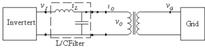
The controlled system in this paper is shown in Fig. 1, which includes inverter module, LC filter, isolating transformer and grid.
Fig. 1. Grid-connected inverter system.
The energy source of the inverter module can be photovoltaic, wind turbine, or fuel cell, etc.. The objective of this paper is to design a current controller for inverter to generate highly qualified output power, io and vo. To obtain output voltage or current free from low-order harmonic distortion, in general, PWM switching method is preferable, however, high frequency components on the switching frequency is mixed in the outputs. Actually, the main disturbances of the controlled systems are pre-existing grid voltage distortion and switching frequency components in the output power. The switching frequency nose is to be attenuated using a well designed LC filter concerning the isolating transformer. However, pre-existing grid voltage distortion still degrades output power quality, and until now, many researched papers to solve the problems have been published which are not sufficient. In this paper, a robust control scheme is presented for attenuating distorted grid voltage effect.
2.1 Modeling of the isolating transformer
An equivalent per phase circuit for the isolating transformerRobust control of grid-connected inverter systems using neural networks
Sung-Hoe Huh*, Moonju Ko
**, Gui-tae Park*, and Ick Choy
*** Dept. of Electrical Engineering, Korea University, Seoul, South Korea (Tel : +82-2-929-5185; E-mail: [email protected])
**Dept. of Control and Instrumentation Eng., Kwangwoon Univ., Seoul, South Korea (Tel : +82-2-940-5157; E-mail: [email protected])
Abstract: Recently, preparing the problems in connection with energy and environment, grid-connected power systems have been intensively researched in the world. In general, the output power of grid-connected inverter (GCI) contains noisy components of inverter switching frequency. Moreover, pre-existing grid voltage disturbances degrade the output power quality. The objective of this paper is to make a GCI output high quality power. A robust current control scheme using neural network is presented in thispaper. To show the feasibility of the proposed scheme, some simulation results are provided.
Keywords: Robust control, grid-connect, inverter, neural network
ICCAS2005 June 2-5, KINTEX, Gyeonggi-Do, Korea
ICCAS2005 June 2-5, KINTEX, Gyeonggi-Do, Korea
under the frequency of 20Khz is shown in Fig. 2. In this circuit, the secondary side circuit elements moved to the primary side, and both sides have same winding impedance values.
Fig. 2. Equivalent circuit of transformer.
Some useful parameters to design LC filter can be defined as: The inverter is connected via a LC filter to an isolating transformer, and the LC filter is to be designed concerning the parameters of the transformer.
(1)
2.2 Inverter filter design []
Assumed that switching frequency is predetermined and fix, then the LC filter components can be calculated based on simple equations.
At first, around the switching frequency, the output current can be expressed by the following equation:
(2) where (3) From the above equation, inductor value is firstly determined to press the current ripple sufficiently. And second stage, to obtain the filter capacitance, the following inequality is to be required.
(4) where (5) Capacitance can be made in the above inequality using the all given values except capacitor impedance.
2.3 Control system
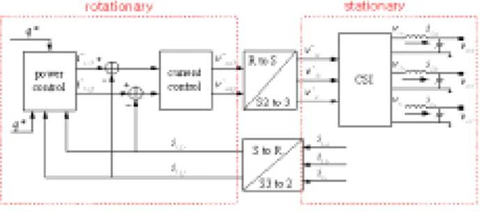
The overall control system is described in Fig. 3, which depicts the power and current controls. For computational convenience, control block is split into two parts, rotating and stationary frames. In general, a currentsource inverter generates superior power quality to that of voltage source type, because the output current quality is less sensitive to the grid voltage quality. From the following equation, differential equation of the currents can be derived.
An arranged differential equation is the following.
From power control block, the current references are
calculated, and current controller generates the desired inverter output voltages. In this figure, PLL is not depicted, however, this block is necessary to find out current voltage angle.
Fig. 3. Controlled system.
3. Robust control scheme
In this paper, a robust current control scheme using neural network is presented.
Neural network is one of universal approximators, which have been proved that any continuous nonlinear function can be approximated by neural network and fuzzy logic systems. Recently, neural network has been very useful appliance in the field of industrial applications and other power electronics. In this controlled system, current control block is a nonlinear mapping that generates voltage references from current errors, and neural network controller approximates the nonlinear mapping with continuous updating its weights.
In general, this block is composed of IP or PI control methods, however, robustness and adaptation abilities are not guaranteed. This is the motivation of this research.
The inputs and outputs in neural controller and overall block diagram are presented in Fig. 4, Fig. 5, respectively.
Fig. 4. Outline of the neural network control.
Fig. 5. Proposed control scheme.
ICCAS2005 June 2-5, KINTEX, Gyeonggi-Do, Korea
4.Simulation results
To show the effectiveness of the proposed scheme, some simulation results are to be shown in this section. The references are balancedthree-phase currents, and the control objectives is to regulate the output current for high quality output power.
At first, current regulation results using PI control is shown in Fig. 5. Because PI control integrates the current errors, steady state error is guaranteed to be zero, however, initial error makes some fluctuation. As compared them, the proposed scheme show some improves, as are Fig. 6,7. Most of all, serious fluctuations of the PI control is drastically removed, and less take time to get to steady state. In this simulation, 5- input, 1-output, 1-hidden layer with 10-neurons neural
network is implemented.
Fig. 5. Controlled signals with PI control.
Fig. 6. D-axis current with neural control.
5.Conclusions
In this paper, a robust controller using neural network for grid-connected inverter system is implemented, and its feasibility is shown in some simulation results.
The objective of this paper is to make a GCI output high quality power.
Simulations are worked with Borland C 4.5 in personal
computer. Through the simulated results, superiorities of the proposed scheme were to be demonstrated that drastically removed serious fluctuations of the PI control and less took time to steady state.
Fig. 7. Q-axis current with neural control.
General type of neural network with 1-hidden layer with 10-neurons neural network is implemented. As future works, more specific analysis of the controlled signals, and experimental results are to be worked.
REFERENCES
[1] T. Kawabata, T. Miyashita, and Y. Yamamoto, “Dead beat control of three phase PWM inverter,” IEEE Trans.
Power Electron., vol. 5, pp.21–28, Jan. 1990.
[2] Y. Ito and S. Kawauchi, “Microprocesor-based robust digital control for UPS with three-phasePWMinverter,”
IEEE Trans. Power Electron., vol.10, pp. 196–204, Mar.
1995.
[3] J. D. Greene and C. A. Gross, “Nonlinear modeling of transformers,”IEEE Trans. Ind. Applicat., vol. 24, pp. 434–438, May/June 1988.
[4] W. Dugui and X. Zheng, “Harmonic model of power transformer,” in Proc. Power Syst. Technol.
(POWERCON’98) Conf., vol. 2, Sept. 1998,pp.
1045–1049.
[5] N. Mohan, T. M. Undeland, and W. P. Robbins, Power
Electronics.New York: Wiley, 1989.
[6] M. Chardokar, D. Divan, and R. Adapa, “Control of parallel connected inverters in stand-alone ac supply systems,” IEEE Trans. Ind. Applicat.,vol. 29, pp. 136–143, Jan./Feb. 1993.
[7] P. Verdelho and G. D. Marques, “Four wire active power filter control circuit with phase locked loop phase angle determination,” in Proc. 7th Int. Conf. Power
Electron. Variable Speed Drives, 1998, 1998, pp.34–39.
[8] N. Bruyant and M. Machmoum, “Simplified digital–analogical control for shunt active power filters under unbalanced conditions,” in Proc. 7th Int. Conf.
Power Electron. Variable Speed Drives, Sept. 1998, pp.
11–16.