ICCAS2005 June 2-5, KINTEX, Gyeonggi-Do, Korea
1. INTRODUCTION
Selective laser sintering (SLS) is a leading process in the new field of solid freeform fabrication (SFF). SLS is an additive process that produces parts directly from CAD model by melting, or sintering layers of a powder together with a laser beam.[1] To develop SLS machine being capable of large size fabrication (800ⅹ1000ⅹ800mm, WⅹDⅹH), the dual laser system should be employed, which can scan divided two regions individually. The laser scanner highly affects the precision and efficiency of SLS machine. The laser scanner is in cooperation with both the generation of scan paths from a sliced section and the scan control to follow the generated paths. Scan paths consist of two parts. One is laser marking from the sliced section, and the other is jumping to next scan path. To generate these scan paths, first of all, scan spacing, the diameter of laser beam, and scan speed have to be considered. Scan paths are generated from these parameters, and scan control is needed to follow generated scan paths precisely and to enable the fabricated surface to absorb fine energy in order to enhance dimensional accuracy. Scan path generation algorithm affects the accuracy and total time of manufacturing. On the characteristics of SLS machine using sintering powder by thermal energy, there is a time delay between the sintered and sintering surface. It results in shrinkage, curling and warpage by thermal distribution. The reduction of thermal distribution can lead to the better precision and quality of the fabricated part. To do this, it is important to scan the surface of powder fast. The shorter the fabricating time in one layer is, the lesser the thermal distribution will be, resulting in a higher quality. To generate scan paths fast, adaptive paths according to the geometrical shape of each layer are needed[2][3][4][5]. Chen[6] developed an intelligent scan method to reduce curling, shrinkage, and growth of the fabricated part. These dimensional errors were solved by optimizing laser power, scan spacing and scan speed of different regions, even though in the same layer. Also Bonus-Z model was developed to compensate bottom growth at the several bottom surfaces. Park[7] enhanced the quality of fabricated part by generating scan path from the directly sliced
section from STL file. It was to compensate the weak points of deteriorating the quality of final part when the scan path was generated from sliced section of STL files. Especially his work remarkably improved the quality of part with complex geometry. Yang et al.[8] developed curling and shrinkage phenomena more by relieving thermal stresses differences between neighboring regions in the same layer. To do this, fractal scan path was generated instead of linear scan path to reduce the difference of thermal distribution. Yang et al.[9] studied effective scan method by generating scan path with offsets from contour. This is to scan inner and outer surface from contour by offset value. It is faster and has the fine surface than those of linear scan paths.
In this paper, the development of SLS machines being capable of large size fabrication (800ⅹ1000ⅹ800 mm, W ⅹ D ⅹH) will be addressed. The dual laser system and the unique scanning device have been designed and built, which employ CO2 lasers and dynamic 3-axis scanners. The
developed system allows scanning a larger planar surface with the desired laser spot size. To evaluate the suggested method, the complex part will be used for the experiment fabrication
2. SCAN METHOD USING SINGLE LASER
2.1 Scan path generation
Scan path is generated from 2D sliced section in commercial software. Fig. 1 shows 3D modeling shape, that is STL file, and Fig. 2 shows sliced section from STL file. From sliced sections, we can get scan points by obtaining intersection points in one layer as shown in Fig. 3.
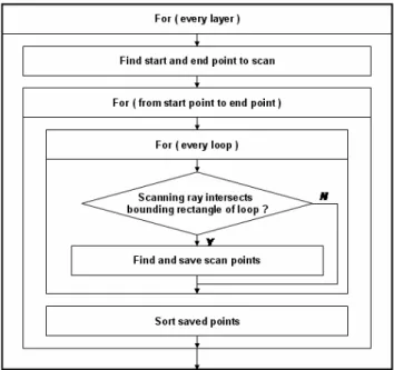
Fig. 4 shows algorithm of scan path generation. In advance, the starting and end points of the layer have to be calculated to scan each layer. Scanning ray moves as scan spacing along perpendicular of the scanning direction. Unnecessary calculation could be removed by calculating only scan points when there are intersection points between each loop and moving scanning ray. After intersection points between scanning ray and the line of each loop are found, we can get final scan points by sorting obtained raw scan points. Laser
Laser Scanning Path Generation for the Fabrication of Large Size Shape
Kyung-Hyun Choi*, and Jae-Won Choi
**, Yang-Hoe Doh
*, Dong-Soo Kim
*** * School of Mechanical Engineering, Cheju National University, Cheju, Korea(Tel : +82-64-754-3713; E-mail: [email protected])
**Department of Mechanical and Intelligent Systems Engineering, Pusan National University, Pusan, Korea (Tel : +82-51-510-1476; E-mail: [email protected])
***Advanced Industrial Technology Department, Korea Institute of Machinery and Materials, Daejeon, Korea (Tel : +82-42-868-7152; E-mail: [email protected])
Abstract: Selective Laser Sintering(SLS) method is one of Rapid Prototyping(RP) technologies. It has been used to fabricate desirable part to sinter powder and stack the fabricated layer. Since the sintering process occurs using infrared laser having high thermal energy, shrinkage and curling of the fabricated part occurs according to thermal distribution. Therefore, the fast scanning path generation is necessary to eliminate the factors of quality deterioration. In case of fabricating larger size parts, the unique scanning device and scanning path generation should be considered. In this paper, the development of SLS machines being capable of large size fabrication(800ⅹ1000ⅹ800 mm, W ⅹD ⅹH) will be addressed. The dual laser system and the unique scanning device have been designed and built, which employ CO2 lasers and dynamic 3-axis scanners. The developed system allows scanning a larger planar surface with the desired laser spot size. Also, to generate the fast scanning paths, adaptive path generation is needed with respect to the shape of each layer, and not simply x, y scanning, but the scanning of arbitrary direction should be enabled. To evaluate the suggested method, the complex part will be used for the experiment fabrication.
Keywords: SFFS(Solid Freeform Fabrication System), Laser Scanning Path
ICCAS2005 June 2-5, KINTEX, Gyeonggi-Do, Korea
beam moves to first scan point with ‘Laser Off’, and to next
scan point with ‘Laser On’. It is simple to mark and jump only by toggle laser according to the order. Fig. 5 shows generated scan path file from algorithm of scan path generation. This file makes the user operate the developed system directly without generating scan path when one wants to fabricate same one as before.
Fig. 1 Modeled part Fig. 2 Sliced sections
Fig. 3 Scanning points and terminologies
Fig. 4 Flowchart of scanning path generation
Fig. 5 Generated scanning path file 2.2 Scan control
It is necessary for the generated scan path to be verified by visualization in commercial software before the fabrication. Also, we need to confirm what type of scan path it is. The neutral file such as IGES as format is needed. All of the generated scan paths are linear, so the IGES file is exported as 106 Entity with Form Number 12, that is Linear Path Entity. Fig. 6 shows an example of generated IGES file and Fig. 7 shows its visualization in commercial software.
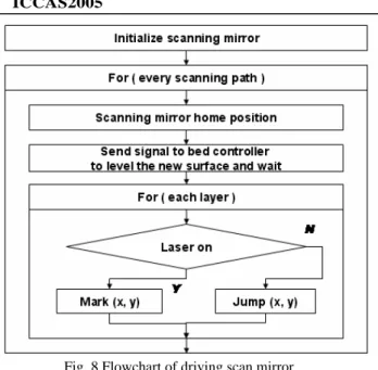
Fig. 8 shows the flowchart to operate scan mirror according to generated scan path. After the scan path is input, scan mirror needs to be initialized and it operates according to the mark and jump command. When sintering is finished in one layer, the system sends ‘recoating’ signal to the bed controller and waits ‘recoating done’ signal. At this time, the mirror has to be positioned at the home position. The fabrication of a part is completed by repeating the above processes.
Fig. 6 Generated IGES file
Fig. 7 Visualization in commercial software
layer No. x y laser on/off param. 1 param.
scanning ray bounding rectangle of loop
bounding rectangle of layer
: start and end points to scan : scanning point
sliced section segment
ICCAS2005 June 2-5, KINTEX, Gyeonggi-Do, Korea
Fig. 8 Flowchart of driving scan mirror
3. SCAN METHOD USING DUAL LASER
To fabricate a large size part, we use dual laser which scans each region to be divided at the Y-axis. The mentioned algorithm of scan path generation in single laser system is available in dual laser system because laser scans each region independently. But the gap at the boundary of neighboring region has to be considered to guarantee the part quality. To do this, we divide two regions along Y-axis and make each laser synchronize the starting position and the time of fabrication.
3.1 Dividing sliced section
To use dual laser, sliced section has to be divided into 2 regions to scan independently. It is divided along Y axis as shown in Fig. 9. Scan path is generated in each divided section as the same as that in single laser system.
3.2 Synchronizing laser control
Fabrication progresses along parallel direction of X axis and Y axis in every two layers repeatedly as shown in Fig. 10.
Fig. 9 Divided sliced section along Y axis
Fig. 10 Synchronizing laser beam at the boundary In the case of parallel direction to Y axis, we adjust the starting position as scan spacing as left side of Fig. 9. At this time, boundary spacing(db) equals half of scan spacing(ds ) and
start direction is kept oppositely. This adjustment enables the fabricated part surface to be homogeneous in comparison to that of the inner surface.
In the case of parallel direction to X axis, it is more difficult for fabricated surface to be homogeneous than in above case because contact position of laser beam on the surface is very small at the same time. It may cause the part surface deteriorate. One of laser control commands somewhat compensates it. We can control laser on and off delay to maintain almost same energy at the surface. It could be done by experience and might be our future work
4. APPLICATION EXAMPLES
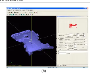
We developed software of scan path generation under Visual C++ MFC environment. The developed software consists of three parts such as STL file viewer, scan path viewer, and parameter window for user to modify and test as shown in Fig. 11. Fig. 11 shows rendered STL file of the part model and scan path in a certain layer at the upper right window. The layer thickness is 0.2mm, scan spacing is 0.5mm and scan direction parallels X and Y axis.
(a)
the left side the right side
Original slicing section Y axis
the left side laser beam the right side laser beam laser beam direction ds : scan spacing db : boundary spacing Y
X
ICCAS2005 June 2-5, KINTEX, Gyeonggi-Do, Korea
(b)
Fig. 11 Scan path and rendered image of the part in two different layers
5. CONCLUSIONS AND FUTURE WORKS
In this paper, we developed algorithm of scan path generation in any direction. It may make scan path adaptive according to the geometrical shape of part. Also we developed scan control algorithm to follow generated scan path well. Finally we developed software which has STL viewer, path viewer, and user-dependent parameter window to make experiment.
We are going to develop faster and more precise scan algorithm and find exact process parameters in real manufacturing. Also, in order to dual laser for fabrication of the large size part we are going to synchronize lasers and develop better way to avoid gaps in the boundary of divided region in its all aspects including CAD and CAM.
.
ACKNOWLEDGMENTS
This work was carried out with the support of the Ministry of Commerce, Industry and Energy, Korea
REFERENCES
[1] Miller,D., Deckard, C., and Williams, J., “Various beam size SLS workstation and enhanced SLS model”, Rapid Prototyping Journal, Vol.3, No.1, pp.4-11, 1997.
[2] Chua C. K., Leong K. F. and Lim C. S., Rapid Prototyping : Principles and Applications, World Scientific Publishing, 2nd Edition, 2003.
[3] Hur S. M., Generation of CAD Data for Rapid Product Development in Reverse Engineering, Pusan National University Graduate School, Ph. D. Thesis, 2002. [4] Kim H. C., Internet-based Intelligent CAD/CAM
System for Rapid Product Development, Pusan National University Graduate School, Ph. D. Thesis, 2003. [5] Yang, H. J., Development of master model-based
fabrication methods for the plastic parts of prototype car, Pusan National University Graduate School, Ph. D. Thesis, 2003.
[6] Chen, K., INTELLIGENT SCANNING IN SELECTIVE LASER SINTERING, The University of Texas at Austin, Ph. D. Thesis, 1998.
[7] Park, S.M., Advanced Data Exchange for Solid Freeform Fabrication, The University of Texas at Austin, Ph. D. Thesis, 2000.
[8] Yang, J., Bin, M., Zhang, X., and Liu, Z., "Fractal scanning path generation and control system for
selective laser sintering(SLS)", International Journal of Machine Tools & Manufacture, Vol. 34, pp. 293-300, 2003.
[9] Yang, Y., Loh, H.T., Fuh, J.H., and Wang, Y.G., "Equidistant path generation for improving scanning efficiency in layered manufacturing", Rapid Prototyping Journal, Vol. 8, No. 1, pp. 30-37, 2002.