P2-112 / S.-l. Yamamoto
IMID 2009 DIGEST • (2 line spacing)
Abstract
We demonstrate an intriguing liquid crystal display (LCD) mode that comprises an optically isotropic liquid crystal (LC) composite incorporating with in-plane electric field geometry. No surface treatment, such as rubbing, is required to fabricate the LCD mode because it is based on an optically isotropic state. The measured response time was of submillisecond order. The LCD mode has several unique features such as fast response, continuous grayscale capability, and a high contrast ratio.
1. Introduction
Recently, Haseba et al. proposed the formation of an optically isotropic LC composite via in situ photopolymerization of crosslinking monomers in the isotropic phase of chiral nematic LC (N*LC).[1,2] It
was experimentally found that this polymer-stabilized composite is optically transparent (isotropic) on a macroscopic scale but has an optically isotropic LC phase with short-range ordering.[1,2] Moreover, the
electro-optic phenomenon observed for this composite is known as the Kerr effect, which is a second-order nonlinear electro-optic effect expressed by
∆ninduced = λ·K·E2 (1)
where λ is the wavelength of the probe light, K is the Kerr constant, and E is the applied electric field.
In this work, we demonstrate an intriguing LCD mode that comprises optically isotropic LC composite incorporating in-plane electric field geometry.
2. Experimental
The host LC material used in this study was a nematic LC (NLC) mixture (host-1) provided by Chisso Petrochemical Co., Ltd. The NLC has the phase sequence Iso.-(48.5ºC)-N on cooling. To introduce chirality into the host NLC, 7wt% chiral dopant, 2,5-bis[4’-(hexyloxy)phenyl-4-carbonyl]-1,4:3,6-dianhydride-D-sorbitol (ISO-(6OBA)2), was
added to host-1, resulting in an N*LC(host-1*). The chemical structures of the chiral dopant used here are presented elsewhere.[3] The formulated host-1* has a
phase sequence Iso.-(48.5ºC)-blue phase I (BPI)-(35.2ºC)-N* on cooling.
To apply the in-plane electric field, we prepared cells sandwiched between two substrate with comb-type interdigitated electrodes on the lower substrate, as shown in Figure 1. The distance between the
Optically isotropic liquid crystal composite incorporating
with in-plane electric field geometry
Shin-ichi Yamamoto
1, Yasuhiro Haseba
1, Takashi Iwata
2, Hiroki Higuchi
3,
Suk-Won Choi
4and Hirotsugu Kikuchi
31
Chisso Petrochemical Corporation, 5-1 Goikaigan, Ichihara, Chiba 290-8551, Japan Tel.:+81-92-583-8902, E-mail: yamamotoshi@cm.kyushu-u.ac.jp
2
NOF Corporations, 5-10 Tokodai, Tsukuba, Ibaraki 300-2635, Japan Tel.:+81-29-847-8892, E-mail: takash
i_iwata
@nof.co.jp3
Institute for Materials Chemistry and Engineering, Kyushu University, 6-1 Kasuga-Koen, Kasuga 816-8580, Japan
Tel.:+81-92-583-7797, E-mail: kikuchi@cm.kyushu-u.ac.jp
4
Department of Display Materials Engineering and Materials Research Center for Information Displays, Kyung Hee University, Yongin-shi, Gyeonggi-do 446-701,
Republic of Korea
Tel: +82-31-201-2256 , E-mail: schoi@khu.ac.kr
P2-112 / S.-l. Yamamoto
• IMID 2009 DIGEST
electrodes on the lower substrates was 10µm. No surface rubbing treatments were performed for either substrate. The cell gap between the two substrates was maintained at approximately 10µm by film spacers.
We fabricated an optically isotropic LC composite, a polymer stabilized isotropic phase of N*LC, as follows. Photo-curable prepolymer mixtures of 43wt% TMPTA (Tokyo Chemical Industry Co., Ltd.) and 57wt% RM257(Merck & Co., Inc) were blended. The precursors of the LC composite constituted 90wt% host-1* and 10wt% blended prepolymers with 0.4wt% of photo-initiator (2,2-dimethoxy-1,2-diphenylethan-1-one, Sigma-Aldrich Corporation). The chemical structures of TMPTA and RM257 used here are described in the literature.[3] The comb-type
sandwiched cell filled with the blended precursor was then irradiated with unpolarized metal halide lamp (UXM-500SX, Ushio Inc.) with a power density of 10mWcm-2 (measured at 365nm) for 3min at 3ºC
above the isotropic phase-LC phase transition temperature of host-1* (in this case 41ºC). During this process, no electric field was applied in the comb-type sandwiched cell.
Figure 1. Illustration for optically isotropic LC composite integrated in-plane electric field geometry.
3. Results and discussion
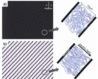
Figure 2 shows the microscopic textures of the optically isotropic LC composite incorporating in-plane electric field geometry; the patterns are obtained under cross polarization with applied fields of 0V and 12Vµm-1 at room temperature. The corresponding molecular orientations, a dark state and a bright state, are also depicted in Figure 1. In the dark state, the optically isotropic LC composite produced a perfect black pattern without surface treatment, as shown in Figure 2(a). Thus, rubbing is not required in fabricating this device because it is based on the isotropic state of optical transparency at the
macroscopic scale but having a optically isotropic LC phase with short-range ordering within a finite size less than the optic wavelength.[1,2,3] Therefore, we
refer to this LC/polymer composite as an optically isotropic LC composite. With an in-plan electric field applied to the lower substrates, LC directors confined within polymer networks were reoriented along the electric field direction (Figure 2(b)). This operation is attributed to the coupling of a local reorientation of the molecules and distortion of the polymer networks.
elec trod e Polarizer elec trod e elec trod e Polarizer
Figure 2. Microscopic texture of optically isotropic LC composite made of host-1* in the sandwiched cell with the comb-type interdigitated electrodes at room temperature, taken under crossed polarizers, in the presence of an applied field of (a) 0 and (b) 12Vµm-1.
Optical anisotropy (∆ninduced) was observed, and the
transmittance gradually increased by optical retardation under cross polarization, as shown in Figure 3(a). The electro-optic operation had analog grayscale capability with a high contrast ratio of more than 3000:1 between the dark and white states. We also measured the response time of the LC composite using a square voltage between 0 and 12 Vrms/µm with
a frequency of 1 kHz. As shown in Figure 3(b), the measured rise time was τrise ~ 0.38 ms and the decay
time was τdecay ~ 0.80 ms for 10~ 90% changes in
transmitted intensity at room temperature. Such a fast response characteristic results from the local reorientation of molecules in small LC clusters as well as strong polymer stabilization. Many researchers and developers have pointed out that a slow decay response is a critical problem for conventional LCDs because the decay response mainly depends on the material properties irrespective of the applied voltage. In our device, the decay response is of
P2-112 / S.-l. Yamamoto
IMID 2009 DIGEST • submicrosecond order; that is, the response is very
fast.
(a)
(b)
Figure. 3 (a)The electro-optic transmittance curve of optically isotropic LC composite made of host-1* in the sandwiched cell with the comb-type interdigitated electrodes at room temperature. (b) Measured response profiles using square voltage at f=1 kHz between 0 and 12 Vrms/µm at room temperature.
4. Summary
This optically isotropic LC composite mode allows for uniform alignment over a large area without employing any additional alignment process. The response is extremely fast compared with conventional LCD modes, and thus the mode is promising for the display of motion in video imagery.
Acknowledgement
This work is supported by a Comprehensive Support Programs for Creation of Regional Innovation from the Japan Science and Technology Agency.
5. References
1. Haseba Y, Kikuchi H, Nagamura T, Kajiyama T, Adv. Mater., 17, 2311 (2005)
2. Haseba Y, Kikuchi H, J. Soc. Inf. Disp., 14, 551 (2006)
3. Choi S W, Yamamoto S I, Haseba Y, Higuchi H and Kikuchi H, Appl. Phys. Lett., 92, 043119 (2008)