ICCAS2005 June 2-5, KINTEX, Gyeonggi-Do, Korea
Load Flow Calculation and Short Circuit Faults Transients in Dispersed Generation Systems
Seyed Hossein Hosseini*, Farhad Shahnia**, and Saeed Tizghadam*** *Azarbaijan Regional Electric Company, Tabriz, Iran
(Tel : +98-914-3134864; E-mail: [email protected])
**Electrical and Computer Engineering Faculty, University of Tabriz, Tabriz, Iran (Tel : +98-411-3393711; E-mail: [email protected])
***Electrical and Computer Engineering Faculty, University of Tabriz, Tabriz, Iran (Tel : +98-411-3849562; E-mail: [email protected])
Abstract: Load flow and short circuit fault transients of a power distribution system with wind turbines as dispersed generation units is presented. Usage of renewable energies such as wind is already a small part of total installed power system in medium and low voltage networks. In this paper, a radial power distribution system with wind turbines is simulated using DIgSILENT PowerFactory software for their influence on load flow and short circuit fault transients. Short fault occurring in dispersed generation systems causes some problems for the system and costumers such as fault level increase or the problems of sudden fluctuations in the current, voltage, power and torque of the double fed induction machine utilized in the wind turbines which have been studied and investigated.
Keywords: Dispersed generation, wind turbines, double fed induction generator, load flow, short circuit fault. 1. INTRODUCTION
In recent years, dispersed generation has been widely used and is expected to become a significant way of exploiting distributed energy resources for supplying power electric demands in the future electric power system. DG units are relatively small in kW to MW range, usually connected to the grid at substations, distribution feeders or at costumer loads which generate power in the form of direct current such as in photovoltaic or fuel cells or in the alternative 50 Hz form such as wind turbines [1-3].
Wind turbines are used more than other DG units while their power generation is also more than the others, some producing 2-4 MW electricity. One of the simplest methods of running a wind generation system is to use an induction generator connected directly to the power grid. Induction generators are the most cost-effective and robust machines for energy conversion; however, they require reactive power especially at startups that can lead to voltage collapse after a fault on the grid. It is well known that the power delivered by wind turbines directly coupled to the grid is not constant as a result of the wind variability. In the absence of storage systems, a fluctuating power supply produced, for example, by gusts, can lead to voltage variations in the grid and flicker. Another disadvantage of most induction machines in wind turbines is that the required reactive power varies with wind speed and time.
To overcome such stability problems, the use of power electronics in wind turbines can be a useful option. For this reason, double fed induction generators (DFIG) are used for wind turbine applications. In the case of variable-speed wind turbines, the problems are ameliorated but the problem of low power quality of the grid due to production of the power converter harmonics arises. One problem with wind power installations is the power quality impact that wind turbines have on the grid, especially weak or rural grids. Not only changes in the wind, but also the wind turbines themselves create power pulsations. This has led to high costs for connecting the wind turbines to the grid, up to about 20% of
the total cost of a wind turbine installation. A possibility which reduces the power quality impact is to use variable speed operation of the turbine by using transistor converters. The power quality can, with this configuration, be improved, however, the cost increases, and at higher wind speeds the variable speed system has a lower efficiency compared with a fixed-speed system [4-7].
Several papers are published on the design, control and characteristics of DFIG based wind turbines on the power grid, each presenting a new model or control system and proving the effects of the wind turbine on the power quality or stability of the power grid [8-11]. In this paper, a built-in model of DFIG based wind turbine is used for load flow calculations of the power system in accordance with the dynamic power demands of the power grid. Also the effects of short circuit faults in the grid are studied on the power load flow. The simulation results are done with dedicated power system simulation tool, DIgSILENT PowerFactory software.
2. WIND TURBINE MODEL
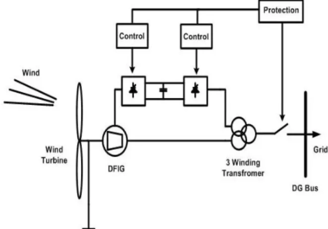
The schematic diagram of the DFIG based wind turbine model simulated in DIgSILENT is shown in Fig. 1.
As it is shown in Fig. 1, the stator output of the induction motor is fed back to a DC voltage bus through a PWM controlled grid side converter and then fed to the rotor of the induction motor through a rotor side PWM controlled converter. The PWM converters are self commutated six pulse bridges. In the built-in DFIG model of DIgSILENT
PowerFactory software, the rotor side converter is modeled
inside the double fed induction generator. Several control system are also applied for protection and control of the converters.
The rotor side converter operates in a stator-flux dq reference model that decomposes the rotor current into active power (q-axis) and reactive power (d-axis) components where two control loops regulate the active and reactive power and current set point as shown in Fig. 2.
Fig. 2. Block diagram of the rotor side converter of DFIG. The grid side converter which operates in AC voltage dq reference uses two control loops to regulate the active and reactive components of the current and the DC voltage as shown in Fig. 3.
Fig. 3. Block diagram of the grid side converter of DFIG. In this paper, the load flow and short circuit fault transients of a radial power distribution system utilizing such a DFIG based wind turbines is studied.
3. LOAD FLOW CALCULATION
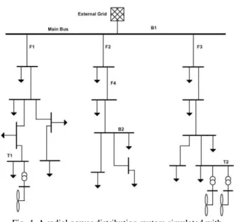
Load flow of wind turbine based dispersed generation systems especially with considering several parameters such as dynamic power demand of the costumers and dynamic wind speed can be too complicated for being solved. In this paper, power load flow of a radial distribution system with several installed wind turbines on different feeders is studied. The schematic diagram of the simulated power system with the wind turbines installation locations is shown in Fig. 2.
Fig. 4. A radial power distribution system simulated with DIgSILENT PowerFactory as the study case.
The results of the load flow calculation simulation are shown in Table 1 where the active and reactive power dispatch and their loadings for some main buses and lines are shown for the system without any wind turbines installed and also the system with wind farms installed with their peak power generation. Also, the peak and mean power demand of the network while the wind turbines are installed and used for generating power are shown in Fig. 5 for dynamic wind speed and load demand.
Table 1. Results of power load flow of the distribution system without any wind turbines installed for some buses.
Buses P(MW) Q(MVar) V(KV) cosϕ
B1 29.61 1.95 62.89 - 0.85 B2 4 0.17 62.75 - 0.97
T1 4.82 0.41 29.66 - 0.79
T2 7.65 0.93 29.72 - 0.81 Table 2. Results of power load flow of the distribution system
without any wind turbines installed for the feeders.
Feeders P(MW) Q(MVar) Loading Factor(%)
F1 13.23 -0.21 78.16
F2 10.02 -0.51 71.21
F3 6.36 0.92 62.9
Table 3. Results of power load flow of the distribution system with all wind turbines installed for some buses.
Buses P(MW) Q(MVar) V(KV) cosϕ
B1 44.21 0.51 62.82 - 0.81
B2 4 0.17 62.70 - 0.84 T1 1 0.1 29.57 - 0.75 T2 2 0.1 29.75 - 0.98
Table 4. Results of power load flow of the distribution system without any wind turbines installed for the feeders.
Feeders P(MW) Q(MVar) Loading Factor(%)
F1 18.14 -0.11 76.69
F2 10.2 -0.51 61.22
F3 16.06 0.11 68.76
Fig. 5. Dynamic load flow of some of the main buses of the system with wind speed and load demand variations. 4. SHORT CIRCUIT FAULT TRANSIENTS Some national standards such as Italian CEI 11-20 propose that the DG units should be automatically disconnected form the public distribution system when the public network undergoes a fault. This is done because when a fault happens, the different existing relays in the power system disconnect the power supply from the fault location but if the DG units are still be feeding the fault, the fault level can increase, leading to damage of electric equipment. In this paper, two different faults are studied on the performance of the wind turbines and the current, voltage and active and reactive power of the power network. Also some characteristics of the DFIGs such as the generator speed and wind power are studied.
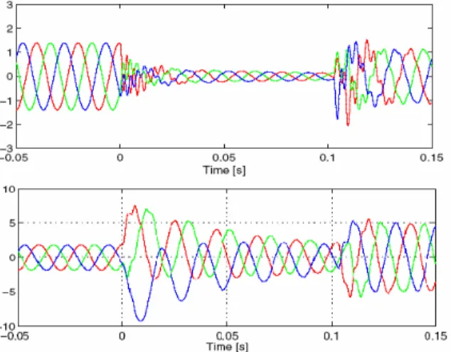
The voltage and current waveforms of the DFIG in short circuit fault time lapse is shown in Fig. 6 where the pre-fault and after-fault conditions are shown. The fault starts at 0 and is cleared at 0.1 seconds.
Fig. 6. Voltage and current waveforms of DFIG during short circuit faults.
In this paper, 2 different fault types, three phase and single phase fault have been studied for the operation of the DFIG of the wind turbine. Each fault consists of a short circuit fault on the bus of one of the wind turbines as a close fault to the wind turbine while the other is a short circuit fault at the middle of feeder F4 shown in Fig. 4. as an arc fault. The first fault starts at 0 seconds and clears at 0.4 seconds and the second fault starts at 2 seconds and clears at 2.1 seconds. After any short circuit fault happens, the protection system controls the operation of the circuit breaker connected to each wind turbine so that at fault situations, the DG units can be disconnected from the utility.
For the three phase short circuit fault, the active and reactive power of the stator, grid side converter and the DFIG are shown in Figures 7-9.
Fig. 7. Active and reactive power of the stator of the DFIG during three phase faults.
Fig. 8. Reactive power of the grid side converter of the DFIG during three phase faults.
Fig. 9. Total active and reactive waveforms of the DFIG during three phase faults.
The current and voltage waveforms of the grid side of the DFIG during three phase fault is also shown in Fig. 10. The induction generator speed and wind power at three phase short circuit fault is also shown in Fig. 11.
Fig. 10.Voltage and current of the grid side of the DFIG during three phase faults.
Fig. 11. Induction generator speed and wind power during three phase faults.
For the single phase short circuit fault, the active and reactive power of the stator, grid side converter and the DFIG are shown in Figures 12-14.
Fig. 12. Active and reactive power of the stator of the DFIG during single phase faults.
Fig. 13. Active and reactive power of the grid side converter of the DFIG during single phase faults.
Fig. 14. Total active and reactive power waveforms of the DFIG during single phase faults.
The current and voltage waveforms of the grid side of the DFIG during three phase fault is also shown in Fig. 15. The induction generator speed and wind power at three phase short circuit fault is also shown in Fig. 16.
Fig. 15.Voltage and current of the grid side of the DFIG during single phase faults.
Fig. 16. Induction generator speed and wind power during single phase faults.
5. CONCLUSION
Load flow of a power distribution system utilizing wind turbines as dispersed generation units was carried out using power system dedicated software, DIgSILENT PowerFactory. Dynamic variations in the wind speed and the power load demand have been also included in the load flow simulations of the case study. Short circuit fault transients are studied for both single phase and three phase faults, close or in the remote area from the wind turbines of the distribution system. The results include the waveforms of the active and reactive power, voltage and current waveforms of the DG units and the power network.
REFERENCES
[1] F.D. Kanellos, N.D. Hatziargyriou, “The effect of variable speed wind turbines on the operation of weak distribution networks”, IEEE Trans. on Energy
Conversion, Vol. 17, No. 4, pp. 543-548, December.
2002.
[2] L.M. Popa, F. Blaabjerg, I. Boldea, “Wind turbine generator modeling and simulation where rotational speed is the controlled variable”, IEEE Trans. on
Industry Applications, Vol. 40, No. 1, pp. 3-10,
Jan./Feb. 2004.
[3] R. Caldon, F. Rossetto, R. Turri, “Analysis of dynamic performance of dispersed generation connected through inverter to distribution system”, 17th Int. Conf. on
Electricity Distribution, CIRED 2003, Paper No. 87,
Barcelona, May 2005.
[4] Z. Chen, E. Spooner, “Grid power quality with vriable speed wind turbines”, IEEE Trans. on Energy
Conversion, Vol. 16, No. 2, pp. 148-153, June 2001.
[5] T. Thiringer, T. Petru, C. Liljegren, “Power quality impact of a sea located hybrid wind park”, IEEE Trans. on
Energy Conversion, Vol. 16, No. 2, pp. 123-127, June
2001.
[6] A.D. Hansen, P. Sorensen, L. Jansoi, J. Bech, “Wind farm modeling for power quality”, 27th IEEE Annual Conf. of
Industrial Electronics Society, IECON’01, pp. 1959-1964,
2001.
[7] P. Sorensen, A.D. Hansen, L. Janosi, J. Bech, B.B. Jansen, “Simulation of interaction between wind farm and power system”, Riso National Laboratory, Roskilde, Dec. 2001. [8] M.A. Poller, “Doubly fed induction machine model for stability
assessment of wind farms”, IEEE PowerTech Conf., Bologna, Italy, June 2003.
[9] A.D. Hansen, P. Sorensen, F. Iov, F. Blaabjerg, “Initialisation of grid connected wind turbine models in power system simulations”, Wind Engineering, Vol. 27, No. 1, pp. 21-38, 2003.
[10] P. Sorensen, A.D. Hansen, P. Christensen, M. Mieritz, J. Bech, B.B. Jansen, H. Nielsen, “Simulation and verification of transient events in large wind power installations”, Riso
National Laboratory, Roskilde, October 2003.
[11] A.D. Hansen, C. Jauch, P. Sorensen, F. Iov, F. Blaabjerg, “Dynamic wind turbine models in power system simulation tool DIgSILENT”, Riso National Laboratory, Roskilde, December 2003.