저작자표시-비영리-변경금지 2.0 대한민국 이용자는 아래의 조건을 따르는 경우에 한하여 자유롭게 l 이 저작물을 복제, 배포, 전송, 전시, 공연 및 방송할 수 있습니다. 다음과 같은 조건을 따라야 합니다: l 귀하는, 이 저작물의 재이용이나 배포의 경우, 이 저작물에 적용된 이용허락조건 을 명확하게 나타내어야 합니다. l 저작권자로부터 별도의 허가를 받으면 이러한 조건들은 적용되지 않습니다. 저작권법에 따른 이용자의 권리는 위의 내용에 의하여 영향을 받지 않습니다. 이것은 이용허락규약(Legal Code)을 이해하기 쉽게 요약한 것입니다. Disclaimer 저작자표시. 귀하는 원저작자를 표시하여야 합니다. 비영리. 귀하는 이 저작물을 영리 목적으로 이용할 수 없습니다. 변경금지. 귀하는 이 저작물을 개작, 변형 또는 가공할 수 없습니다.
Thesis for the Degree of Doctor of Philosophy
Preparation, characterization and
application of bacterial cellulose based
functional nanocomposites
박테리아 셀룰로오스 기반
기능성 나노복합체의 제조와 특성 및 응용 연구
August 2016
By
Park, Minsung
Department of Biosystems & Biomaterials
Science and Engineering
Thesis for the Degree of Doctor of Philosophy
Preparation, characterization and
application of bacterial cellulose based
functional nanocomposites
August 2016
By
Park, Minsung
Department of Biosystems & Biomaterials
Science and Engineering
Thesis for the Degree of Doctor of Philosophy
Preparation, characterization, and
application of bacterial cellulose based
functional nanocomposites
A Thesis Submitted to the Faculty of Seoul National University
in Partial Fulfillment of the Requirements for
the Degree of Doctor of Philosophy
By
Park, Minsung
Advisor : Professor Jinho Hyun, Ph.D.
August 2016
Department of Biosystems & Biomaterials
Science and Engineering
Department of Biosystems & Biomaterials
Science and Engineering
SEOUL NATIONAL UNIVERSITY
Supervisory Committee Approval
of Thesis submitted by Park, Minsung
This thesis has been read by each member of the following
supervisory committee and has been found to be satisfactory.
Chairman of Committee :
Lee, Kihoon
Vice Chairman of Committee :
Hyun, Jinho
Member of Committee :
Ki, Chang Seok
Member of Committee :
Youn, Hye Jung
Member of Committee :
Preparation, characterization and application of
bacterial cellulose based functional nanocomposites
박테리아 셀룰로오스 기반
기능성 나노복합체의 제조와 특성 및 응용 연구
지도교수 현 진 호
이 논문을 박사 학위논문으로 제출함
2016년 5월
서울대학교 대학원
바이오시스템·소재학부
바이오소재전공
박 민 성
박민성의 박사 학위논문을 인준함
2016년 6월
위 원 장 이 기 훈 (인)
부위원장 현 진 호 (인)
위 원 기 창 석 (인)
위 원 윤 혜 정 (인)
위 원 김 재 환 (인)
Abstract
Bacterial cellulose (BC)-based nanocomposites incorporated with inorganic nanoparticles and biopolymers were fabricated by employing suitable synthesis strategies, and their potential applications were investigated. Firstly, a series of BC nanocomposites containing inorganic nanoparticles were synthesized using appropriate methods. BC magnetite nanocomposites (MNP-BC) were biosynthesized by incubating bacteria in a medium containing magnetic nanoparticles (MNPs). Subsequently, polyaniline (PANi) was synthesized on the MNPs-BC nanocomposites by carrying out oxidative polymerization of aniline. Magnetic and electrical measurements confirmed that the MNP-PANI-BC exhibited the potential to be used as an electromagnetic shielding material. Silicon nanoparticles (SiNPs)-BC nanocomposites were prepared by dipping BC in the SiNPs dispersion.SiNPs were uniformly attached to the BC pellicle surfaces along the nanofibers. The conductive PANi-Si-BC composite exhibited stable conductivity under repetitive bending stress, confirming its potential for flexible anode application. Gold nanoparticles (AuNPs)-BC nanocomposites were prepared by employing the in situ polymerization of AuNPs on the BC fibers, which could act as a template and an immobilized reducing agent. The surface-enhanced Raman scattering signals corresponding to molecules to be detected on the AuNPs-BC nanocomposite were significantly enhanced due to the spatial deformation of the composite. Secondly, a series of BC nanocomposites containing biopolymers were synthesized with TEMPO-oxidized bacterial cellulose (TOBC). TOBC fibers were obtained using a TEMPO/NaBr/NaClO system at pH 10 and room temperature. The fibrillated
ii
TOBCs mixed with alginate were cross-linked in the presence of Ca2+ solution to form hydrogel composites. Alginate/TOBC hydrogel composites exhibited improved mechanical and chemical resistance, indicating that the hydrogel could be used for cell encapsulation applications. Elastin-like polypeptide (ELP)-BC composites were synthesized, which could be used as a thermosensitive hydrogel for cell encapsulation applications. Positively charged ELP was used as a polymeric cross-linker for conjugating with negatively charged cellulose nanofibers. Hydrogel formation was triggered by increasing the temperature, and the hydrogel was converted to the liquid phase by decreasing the temperature.
Keywords: Bacterial cellulose nanocomposite, Inorganic nanoparticles,
Magnetite nanoparticles, Silicon nanoparticles, Gold nanoparticles, Biopolymer, Alginate, Elastin-like polypeptide
iii
CONTENTS
Chapter 1
Introduction ... 1
Chapter 2
Literature survey ... 7
2.1.
Cellulose nanofibers
...8
2.1.1. Cellulose ... 82.1.2. Processes of cellulose nanofibers preparation ... 12
2.1.3. Three types of cellulose nanofibers ... 12
2.1.3.1. Cellulose nanocrystals ... 17
2.1.3.2. Cellulose nanofibrils ... 17
2.1.3.3. Bacterial cellulose ... 19
2.1.4.Surface modification of cellulose nanofibers ... 20
2.2.
Bacterial cellulose
(BC)
...23
2.2.1. General information of BC... 23
2.2.2. Biosynthesis process of BC ... 25
2.2.3. Factors affecting the production capacity of BC ... 28
2.2.4. Productivity of BC ... 30
2.2.4.1. The species and genetic modification of bacteria ... 31
iv
2.2.5.
Characteristic differences between the plant cellulose and
BC ... 34
2.2.6. Applications of BC ... 38
2.2.6.1. Composites with high mechanical strength ... 38
2.2.6.2. Separation and waste purifications ... 39
2.2.6.3. Conducting materials and electrical devices ... 39
2.2.6.4. Biomedical applications ... 41
2.2.6.5. Food applications ... 42
Chapter 3
Electromagnetic BC nanocomposite using magnetite
nanoclusters and polyaniline ... 44
3.1. Introduction ... 45
3.2.
Materials and method ... 48
3.2.1. Preparation of highly dispersive magnetite nanoparticles (MNPs) ... 48
3.2.2. Biosynthesis of MNP-incorporated BC (MNP-BC) nanocomposites ... 49
3.2.3. Polymerization of polyaniline (PANi) on the MNP-BC (PANi-MNP-BC) nanocomposites ... 49
3.2.4. Characterizations of nanocomposites ... 50
v
3.3.1. Enhancement of the colloidal stability of MNP solutions ... 51
3.3.2. Biosynthesis of MNP-BC nanocomposites... 54
3.3.3. Synthesis of PANi-MNP-BC nanocomposites ... 58
3.3.4. Electromagnetic properties of nanocomposites ... 64
3.4. Summary ... 66
Chapter 4
Flexible conductive BC combined with silicon
nanoparticles and polyaniline ... 67
4.1.
Introduction ... 68
4.2.
Materials and method ... 71
4.2.1. Preparation of the silicon nanoparticle-embedded BC (Si-BC) nanocomposites ... 71
4.2.2. Polyaniline (PANi) polymerization with BC (PANi-BC) and Si-BC nanocomposites (PANi-Si-Si-BC) ... 71
4.2.3. Characterization of nanocomposites... 72
4.3. Results and discussion ... 74
4.3.1. Preparation of the Si-BC nanocomposites... 74
4.3.2. Synthesis of PANi-Si-BC nanocomposites ... 80
4.3.3.Conductivity of nanocomposite under bending stress ... 92
vi
Chapter 5
Surface-enhanced Raman scattering sensor based on a
BC hydrogel ... 95
5.1.
Introduction ... 96
5.2.
Materials and method ... 99
5.2.1. In situ synthesis of gold nanoparticles (AuNPs)-BC ... 99
5.2.2. Characterization of AuNPs-BC nanocomposites ... 99
5.2.3. SERS experiments ... 100
5.3. Results and discussion ... 100
5.3.1. In situ synthesis of AuNPs-BC hydrogel ... 100
5.3.2. SERS measurement using undeformed AuNPs-BC ... 105
5.3.3. SERS measurement using deformed AuNPs-BC ... 110
5.3.4. Detection of molecules with weak affinity to Au surfaces ... 114
5.4. Summary ... 116
Chapter 6
Oxidized BC/alginate hydrogel for cell encapsulation .. 117
6.1.
Introduction ... 118
6.2.
Materials and method ... 121
6.2.1. Preparation of TEMPO-mediated oxidized BC (TOBC) ... 121
vii
6.2.3. Characterization of alginate/TOBC beads ... 122
6.2.4. Viability and proliferation of encapsulated cells ... 123
6.3. Results and discussion ... 123
6.3.1. Preparation of alginate/TOBC beads ... 123
6.3.2. Mechanical and chemical stability of alginate/TOBC ... 131
6.3.3. Permeability of alginate/TOBC beads ... 135
6.3.4. Viability and proliferation of encapsulated cells ... 139
6.4. Summary ... 142
Chapter 7
Thermoresponsive hybrid hydrogel of oxidized BC using
a elastin like polypeptide ... 143
7.1.
Introduction ... 144
7.2.
Materials and method ... 147
7.2.1. Elastin like polypeptide (ELP) synthesis ... 147
7.2.2. Sol-gel transition ... 147
7.2.3. Characterization of ELP/TOBC ... 147
7.2.4. Cell viability and proliferation ... 149
7.3. Results and discussion ... 151
7.3.1. Gel formation of ELP/TOBC ... 151
7.3.2. Rheological analysis of ELP/TOBC hydrogel ... 154
viii
7.3.4. Mechanism of TOBC/ELP hydrogel formation ... 160 7.3.5. Viability and proliferation of cells ... 166
7.4. Summary ... 168
Chapter 8
Conclusions ... 169
ix
List of Tables
x
List of Figures
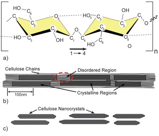
Figure 2-1. Wood hierarchical structure: from tree to cellulose. ... 9 Figure 2-2. Schematics of (a) single cellulose chain repeating unit, showing
the directionality of the β-(1–4) linkage and intrachain hydrogen bonding (dotted line), (b) idealized cellulose microfibril showing one of the suggested configurations of the crystalline and amorphous regions, and (c) cellulose nanocrystals after acid hydrolysis dissolved the disordered regions. ... 11 Figure 2-3. Top-down process for obtaining cellulose nanofibers (CNC and
CNF). ... 13 Figure 2-4. Bottom up process for obtaining cellulose nanofibers (Bacterial cellulose) ... 14 Figure 2-5. Transmission electron micrographs of a) CNFs and b) CNCs, c) scanning electron micrograph of BC ... 16 Figure 2-6. Schematic images of the major metabolic pathways of G.xylinum
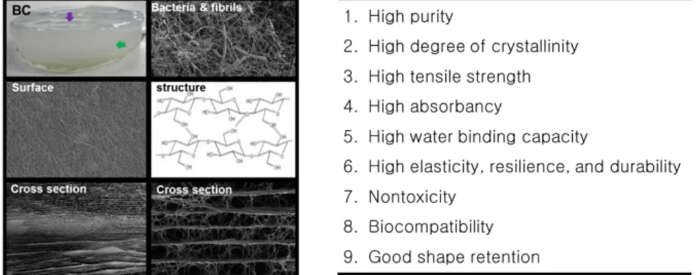
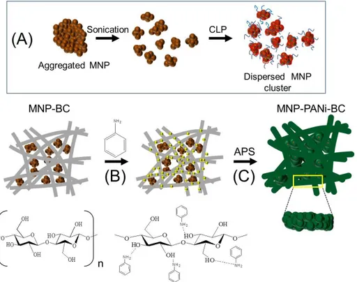
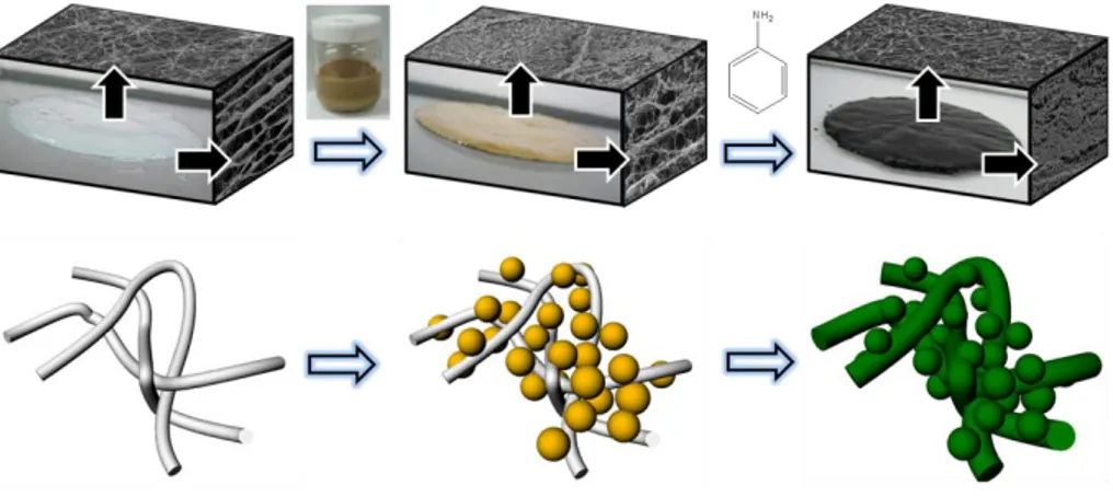
and the assembly of cellulose molecules into nanoribbon. ... 27 Figure 2-7. BC produced under static and agitated conditions. ... 33 Figure 2-8. General overview of bacterial cellulose structural organization. 36 Figure 2-9. Unique structures and properties of bacterial cellulose ... 37 Figure 3-1. Preparation of electromagnetic BC nanocomposites. (A)
xi
Dispersion mechanism of MNPs using CLP stabilizer, (B) addition of aniline to BC membrane, and (C) oxidative polymerization by
ammonium persulfate ... 47 Figure 3-2. (A) Dispersion mechanism of MNP using CLP stabilizer, (B)
Optical images of an aqueous MNPs solution at different
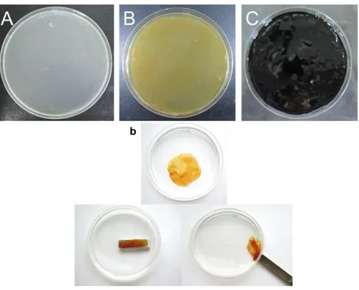
concentration of CLP, (C) Filtration test of (a) MNP solution and (b) CLP-modified MNP solution, and (D) Relative UV absorbance of MNP and CLP-MNP solution as a function of storage time (SD, n=5). ... 53 Figure 3-3. Optical images of (A) pure BC, (B) MNP-BC, and (C)
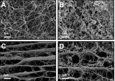
PANi-MNP-BC. (b) is optical images for showing the magnetic property of MNP-BC using magnetic bar. ... 56 Figure 3-4. SEM images of (A) pure BC, (B) MNP-BC without CLP and (C)
MNP-BC with CLP. ... 57 Figure 3-5. SEM images of (A) PANi-BC and (B) PANi-MNP-BC, (C)
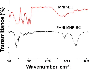
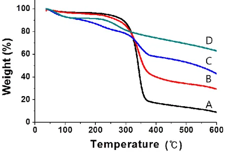
magnified image of A and, (D) magnified image of B. ... 59 Figure 3-6. FT-IR spectra of (A) BC and (B) PANi-MNP-BC. ... 61 Figure 3-7. TGA curves of (A) BC, (B) MNP-BC, (C) PANi-BC and (D)
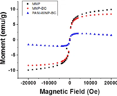
PANi-MNP-BC. ... 63 Figure 3-8. Magnetic hysteresis curves of BC nanocomposites... 65 Figure 4-1. Schematic representation of the process for preparing PANi-Si-BC
xii
composite. ... 70 Figure 4-2. Hydroxyl groups were introduced on the surface of SiNPs as a
result of modification with phytic acid. Hydroxyl groups of SiNPs can form hydrogen bonds with BC nanofibers ... 75 Figure 4-3. Optical images of (A) pure BC, (B) Si-BC composite and (C) the
weight percentage of SiNPs bound to BC in Si-BC composite as a function of incubation time in SiNP-dispersion solution. ... 76 Figure 4-4. FE-SEM images of BC and Si-BC composite. (A) Surface and (C) cross section of freeze-dried BC. (B) Surface and (D) cross section of freeze-dried Si-BC composite ... 79 Figure 4-5. After adding aniline monomer and APS, PANi was polymerized
on both BC nanofibers and SiNPs. The BC structure can serve as the template for both the adsorption of SiNPs and the polymerization of PANi ... 81 Figure 4-6. (A and B) Conductivity and contents of PANi/BC with moral
ratios of APS to anliline from 0.25 to 2. (Polymerization time was 1h and reaction temperature was 20 ℃), (C and D) Conductivity and contents of PANi-Si-BC with reaction time from 0.5 h to 2 h. (Molar ratio of oxidant (APS) to monomer (aniline) was 1 and reaction temperature was 20 ℃), and (E and F) Conductivity and contents of PANi-Si-BC with different reaction temperature 5 ℃ and 30 ℃. (Molar ratio of oxidant (APS) to monomer (aniline) was 1 and
xiii
reaction time was 1h ... 82 Figure 4-7. SEM images of composites. (A) Surface image of PANi-BC, (B)
surface image of PANi-Si-BC, and (C) cross sectional images of freeze-dried PANi-Si-BC ... 84 Figure 4-8. TEM images of composites. (A) Si-BC and (B) PANi-Si without
phytic acid. (C) PANi-Si and (D) PANi-Si-BC with phytic acid ... 85 Figure 4-9. XRD patterns of composites. (A) SiNPs, BC, PANi-BC, and
PANi-Si-BC. (B) Change of crystallinity after the incorporation of SiNPs in BC ... 87 Figure 4-10. Thermal stability of the composites. Thermogravimetric curves
of BC, Si-BC and PANi-Si-BC were obtained using 10 mg of a vacuum dried sample in the range of temperature from 25 °C to 600 °C at a heating rate of 10 °C min−1 under flowing nitrogen ... 88 Figure 4-11. Effect of phytic acid on the composites. (A) Morphological
change and (B) the thermal stability of composites ... 91 Figure 4-12. Electrical stability of the composites to bending stress. (A)
Optical images of bending process using UTM and parameters for the calculation of the bending radius, (B) resistance variation of PANi-Si-BC composite for changes in bending radius, and (C) the percentage of resistance change of the composite according to bending cycles up to 100 cycles ... 93
xiv
Figure 5-1. Schematic representation of the process for preparing AuNPs-BC hydrogel ... 98 Figure 5-2. Preparation of highly dispersed AuNPs-BC. Optical image of
normal BC (A) and BC (B). (C) Absorption spectra of AuNPs-BC and normal AuNPs-BC and (D) characteristic XRD peaks of AuNPs-AuNPs-BC and normal BC... 102 Figure 5-3. TEM images of AuNPs-BC synthesized with different reaction
time. (A) 5, (B) 30 and (C) 60 min. Inserted micrographs are SEM images of each samples. (D) EDS spectrum from SEM image of sample (B) ... 104 Figure 5-4. The multilayer structure of the BC hydrogel. (A) The
cross-sectional SEM image of the freeze-dried BC hydrogel, (B) spacing between BC layers, and (C) the thickness of the BC hydrogel as a function of cultivation time ... 106 Figure 5-5. SERS measurement with undeformed AuNPs-BC hydrogel. (A)
Typical Raman spectrum 4-FBT on AuNPs-glass and undeformed AuNPs-BC. (B) Effect of layer number on SERS intensity. SERS signal at 1075 cm-1 was compared ... 107 Figure 5-6. SERS spectra of different concentrations of 4-FBT obtained with
(A) two dimensional AuNPs-attached glass substrate, and (B)
undeformed AuNPs-BC ... 109 Figure 5-7. FE-SEM images of AuNPs-BC composites. Top view (A) and
xv
cross-section (B) of hydrogel-state of Au30-BC. Top view (C) and cross-section (D) of spatially deformed Au30-BC ... 111 Figure 5-8. Effect of spatial deformation of AuNPs-BC hydrogel on SERS
signal. SERS spectra of 4-FBT obtained with undeformed AuNP-BC, and spatially deformed AuNP-BC. 4-FBT concentration: 10-3 M .... 112 Figure 5-9. Detection of 4-FBT with AuNPs-BC composites (A) Schematic
description for additional enhancement of SERS in case of the molecules which have strong affinity to noble metal surface such as 4-FBT (B) SERS spectra of 4-4-FBT obtained with undeformed AuNP-BC substrates, (C) SERS spectra of 4-FBT obtained with spatially deformed AuNP-BC substrates, and (D) SERS intensities comparison for three substrates ... 113 Figure 5-10. Detection of PAA with AuNPs-BC composites (A) Schematic
description for additional enhancement of SERS in case of molecules which have weak affinity to noble metal surface such as PAA (B) SERS spectra of PAA obtained with unmodified AuNP-BC substrates and (C) SERS spectra of PAA obtained with spatial deformed AuNP-BC substrates (D) SERS spectrum of PAA with concentration of 1 x 10⁻⁷ M ... 115 Figure 6-1. Schematic representation of alginate and TOBC beads. (A)
Optical microscopy image of alginate bead and scheme of surface structure of alginate bead, (B) Scheme of the structure of egg-box
xvi
junction zones of alginate. (C) optical microscopy image of alginate/TOBC bead and scheme of surface structure of
alginate/TOBC bead, (D) Scheme of the structure of egg-box junction zones of alginate/TOBC ... 120 Figure 6-2. Selective oxidation of C6 primary hydroxyls of cellulose to
carboxylate groups by TEMPO/NaBr/NaClO oxidation in water at pH 10. (A) Chemical structures of pure BC and TOBC, (B) A relationship between the amount of NaClO and the carboxylate content of the oxidized cellulose, (C) FT-IR spectra for pure BC and TOBC, and (D) X-ray diffraction patterns of the pure BC and TOBC ... 125 Figure 6-3. Preparation of the TOBC. (A) Optical image of pure BC, (B) TEM images of pure BC, and (C) TOBC ... 128 Figure 6-4. SEM images of surface morphology of alginate/TOBC
microbeads regarding the TOBC content. (A) alginate beads, (B) alginate /TOBC10 beads and (C) alginate /TOBC20 beads. Inserted micrographs are optical images of each samples. (D~F) are magnified images of (A~C) ... 129 Figure 6-5. (A) FT-IR spectra for alginate/TOBC composites with various
cellulose contents. (B) XRD patterns for alginate/TOBC composites with various TOBC contents ... 130 Figure 6-6. (A) Compressive stress-strain curves for various alginate/TOBC
xvii
Figure 6-7. Microscopy images of alginate and alginate/TOBC20 microbeads as formed (A, D), after being exposed to 40 mM sodium citrate in 6min(B, E) and 60 min (C, F). Scale bar = 500 μm (G) SEM images of alginate/TOBC20 microbeads after being exposed to 40 mM sodium citrate in 60 min. (H) is magnified images of (G) ... 134 Figure 6-8. Fluorescence microscopic images for permeability assessment of
various alginate/TOBC microbeads. Alginate beads with 4 kDa FITC-Dextran (A) and 150 kDa FITC-FITC-Dextran (B) was immersed in water. After 30 min, 4 kDa FITC-Dextran was released out of the beads (A2).
150 kDa FITC-Dextran could not be released out of the beads. (B2).
(C) and (D) are alginate/TOBC10 samples. (E) and (F) are
alginate/TOBC20 samples ... 137 Figure 6-9. Confocal microscopy section images for permeability assessment
of various alginate/TOBC microbeads. Alginate beads incubated with 4 kDa FITC-Dextran (A) and 150 kDa FITC-Dextran (B).
Alginate/TOBC10 beads incubated with 4 kDa FITC-Dextran (C) and 150 kDa FITC-Dextran (D). Alginate/TOBC20 beads incubated with 4 kDa FITC-Dextran (E) and 150 kDa FITC-Dextran (F). Scale bar = 50 μm ... 138 Figure 6-10. Optical microscopy images of cells encapsulated in alginate (A),
alginate/TOBC (B), and alginate/TOBC20 (C). Cell numbers for various alginate/TOBC beads as function of cultured days. Scale bar=250 μm ... 140
xviii
Figure 6-11. After recovering the cells from beads, Live/Dead staining were conducted. The fluorescence images are the staining results of cells encapsulated in alginate (A), alginate/TOBC10 (B), and
alginate/TOBC20 beads (C). Scale bar=250 μm ... 141 Figure 7-1. Schematic representation of the process for preparing ELP/BC
hydrogel ... 146 Figure 7-2. Temperature-triggered sol-gel transition of the ELP/TOBC
complex. (A) TOBC only, (B) ELP only, and (C) ELP/TOBC ... 152 Figure 7-3. Turbidity variations of ELP (A) and ELP/TOBC (B) solution as a
function of temperature (OD at 350 nm, Heating: 1 °C/min) ... 153 Figure 7-4. Oscillatory temperature ramp measurements to confirm hydrogel
formation. (A) ELP/TOBC complex, (B) pure TOBC solution, (C) pure ELP solution. (Heating rate: 2 °C /min. Concentration of samples: 2 wt%) ... 156 Figure 7-5. FE-SEM images of freeze-dried TOBC (A and A1), ELP/TOBC
solution (B and B1), and ELP/TOBC shrunken hydrogel (C and C1).
Schematic representation of TOBC (A2), ELP/TOBC solution (B2),
and ELP/TOBC hydrogel (C2) ... 159
Figure 7-6. (A) Zeta potential for individual biopolymers and biopolymer composites at 20 °C, and (B) AFM images of TOBC and ELP/TOBC composites ... 161
xix
Figure 7-7. Effect of pH at pH 12 on the formation of ELP/TOBC hydrogels. The ELP/TOBC solution was adjusted to pH 12 to eliminate positive charges on the ELP molecules. The resulted in the inability to form a hydrogel despite increased temperature ... 164 Figure 7-8. CD spectra of ELP/TOBC and ELP obtained at different
temperatures in water. ELP concentration was 0.5 mg/mL in both the ELP/TOBC and pure ELP solutions ... 165 Figure 7-9. (A) MTT results of ELP/TOBC solution, (B, C) Fluorescence
microscopic images of fibroblast cells encapsulated in a ELP/TOBC hydrogel after (B) 1 day and (C) 7 days of incubation (cells were live/ dead stained) ... 167
1
Chapter 1
2
1. Introduction
Biopolymer-based nanocomposite materials have attracted significant attention in many industries owing to their impressive and ecofriendly properties [1]. Bio-based materials prepared using natural rubber [2-5], chitin or chitosan [6-9], polylactic acid [10], polyhydroxybutyrate [11], alginate [12-14], and cellulose [15, 16] have been extensively investigated. In particular, cellulose has received significant attention owing to its abundance in nature, sustainability, low cost, biosafety, biodegradability, and high potential in various applications [17]. Natural cellulose-based materials have been used for engineering and building materials as well as in forest products, paper, and textiles for thousands of years [18]. In the last decades, there have been several efforts to reduce the diameter of cellulose fibers to prepare cellulose nanofibers. Cellulose nanofibers are one of the most attractive materials that could satisfy the increasing demands for high-performance materials owing to its excellent mechanical properties, biocompatibility, tailorable surface modification, and renewable nature [19]. Cellulose nanofibers can be divided into three types: cellulose nanocrystals (CNCs), cellulose nanofibrils (CNFs), and bacterial cellulose (BC) [20, 21].
Among these materials, BC exhibiting unique structural features is considered an ideal nanomaterial for fabricating composites with various materials [22]. BC exhibits an ultrafine fibrous nano-sized three-dimensional (3D) network structure, which could serve as a potential reinforcing matrix in
3
composites. The well-arranged web-shaped fibrous network structure of BC fibers can bind or encage with nanoparticles. Besides, the presence of hydroxyl groups in the cellulose chain allows it to interact with other hydrophilic materials to form stable composites [23].
The preparation of BC-based nanocomposites could be categorized into four different methods: (1) biosynthesis of BC in a medium containing nanoparticles, (2) dipping BC in nanoparticles suspension, (3) in-situ synthesis of nanoparticles on the BC fiber surfaces, and (4) blending of modified cellulose with other biopolymers. Biosynthesized BC composites can be prepared by adding functional materials into the culture medium. Dipping of BC in the nanoparticle suspended solution is a simple method. However, it is difficult to obtain a uniformly distributed nanocomposite since nanoparticles cannot be diffused through the BC layers. The in-situ synthesis method enables the production of composites with a high density of functional materials. In this process, BC nanofibers are used not only as a template, but also as an immobilized reducing agent for synthesizing nanomaterials. Meanwhile, the highly networked BC fibers could be surface-modified and individually dispersed in aqueous solutions. In the modification and blending method, these dispersed BC nanofibers are mixed with other biopolymers to form a stable gel-like structure.
In this thesis, a series of BC based nanocomposites incorporated with inorganic nanoparticles or biopolymers and their potential electronics, sensor,
4
and medical applications are discussed. Appropriate methods for the synthesis of BC-based nanocomposites were designed by choosing functional materials for forming the composites with BC depending on the required applications. The best method for preparing composites was selected from the methods mentioned above.
1. Magnetite nanoparticles (MNPs)-BC nanocomposite by biosynthesis method.
An electromagnetic BC composite was synthesized by culturing
Gluconacetobacter xylinus in a medium containing MNPs. Using comb-like
polymer (CLP) as a polymer surfactant, the magnetite nanoparticles were stably dispersed in the culture medium as magnetite nanoclusters (MNCs). Subsequently, PANi was synthesized on the magnetic BC fibers by chemical oxidative polymerization. The morphology and electromagnetic properties of the BC nanocomposite were investigated.
2. Silicon nanoparticles (SiNPs)-BC nanocomposite by dipping method. A flexible conductive BC composite was synthesized by dipping BC in SiNPs suspended solution. BC was used as a template for binding SiNPs. Subsequently, PANi was formed on the modified SiNPs and BC fibers by in
situ polymerization of aniline monomers. The morphology and the electrical
5
3. Gold nanoparticles (AuNPs)-BC nanocomposite by in situ synthesis. BC hydrogels containing AuNPs were prepared by in situ synthesis method. BC nanofibers were used not only as a template, but also as an immobilized reducing agent for preparing the AuNPs-BC hydrogel. The increase in the surface-enhanced Raman scattering (SERS) hot spot density driven by the spatial deformation of AuNPs-BC hydrogels is discussed. 4. Alginate/BC nanocomposite using modified BC fibers
Micro-hydrogels were prepared using BC nanofibers and alginate. TEMPO-mediated oxidized bacterial cellulose (TOBC) was used to improve the mechanical and chemical stability of the alginate hydrogel. The fibrillated TOBCs mixed with alginate were cross-linked in the presence of Ca2+ solution to form hydrogel composites. The mechanical and chemical stability of composites were investigated. In addition, the viability of the cells encapsulated in the alginate/TOBC composite was investigated for examining the potential biomedical applications of the composite.
5. Elastin-like polypeptide (ELP)/BC nanocomposite using modified BC fibers
A thermoresponsive polysaccharide hydrogel based on nanofibrous cellulose and ELP was prepared. Well-dispersed BC nanofibers were obtained by TEMPO mediated oxidation method. ELPs in the composite folded and
6
coacervated when the temperature increased above Tt, causing TOBCs to rope
together and form a porous hybrid hydrogel of ELP and TOBC. Morphological and conformational changes of the composites were analyzed, and the biocompatibility of the composites for cell encapsulation was investigated.
7
Chapter 2
8
2. Literature survey
2.1. Cellulose nanofibers
2.1.1. Cellulose
Cellulose is considered to be the most abundant biopolymer and an important source of sustainable future as alternatives to synthetic products [24]. The origin of the word ‘material’ is known to be driven from the Latin for ‘trunk of tree’. It shows that there is a deep relationship with the wood and material [18]. Indeed, Wood containing cellulose has been used as the most representative material for a long time as an energy source, clothing, and building materials like timber for house, ship and other various fields. Also, since the Egyptian papyri as a paper, cellulose products have played an important role in the recording of culture [1]. In nature, cellulose is synthesized in large amounts by plants, where it is an essential component of the cell walls. Cellulose secreted as an extracellular product imparts mechanical strength to the cell wall and determines the direction of cell growth [20]. Wood hierarchical structure from tree to cellulose is shown in figure 2-1 [25].
Cellulose is composed of carbon, hydrogen and oxygen and it is classified carbohydrate. The repeat unit of the cellulose is cellobiose to comprise two anhydroglucose rings joined via a β-1,4 glycosidic linkage. Native cellulose is typically called cellulose I. This cellulose I form comprises
9
10
two allomorphs, called cellulose Iα and Iβ [20, 26]. The ratio of cellulose Iα and Iβ is known to differ according to plant species, but cellulose Iα is rich in the bacterial cellulose [20, 27]. The crystalline structures of cellulose I allomorphs have been characterized with the sophisticated hydrogen bonding system which does not allow cellulose to be dissolved in typical aqueous solvents immediately (figure 2-2) [20]. In addition, the stable crystalline structure makes cellulose have no melting point. Due to this unique structural feature, cellulose chains are highly stiff in the axial direction, which is essential property for the reinforcing roles of fiber in a composite [28].
Wood pulp have been used for some industrial feedstock such as the production of paper and cardboard, cellulose regeneration, and the large scale synthesis of cellulose derivatives. Apart from plants, some bacteria, fungi, and algae produce cellulose as well. Among the bacteria to synthesize the cellulose, Gluconacetobacter xylinum (G. xylinum) effectively synthesizes cellulose as a primary metabolic product. They are commonly found on fruits and can be easily cultivated under laboratory conditions [29].
11
Figure 2-2. Schematics of (a) single cellulose chain repeating unit, showing the directionality of the β-(1–4) linkage and intrachain hydrogen bonding (dotted line), (b) idealized cellulose microfibril showing one of the suggested configurations of the crystalline and amorphous regions, and (c) cellulose nanocrystals after acid hydrolysis dissolved the disordered regions [20].
12
2.1.2. Processes of cellulose nanofibers preparation
In the last decades, there have been efforts to reduce the diameter of wood fibers. As a first effort, a micro-fibrillated cellulose (MFC) was developed in the early 1980s [18, 30]. Such isolated cellulosic materials have nanometer sized diameter are referred to as cellulose nanofibers. Today, there are two different ways to prepare cellulose nanofibers with controlled fiber diameters [31].
One is Top-down process involving physical, chemical, and enzymatic method for producing cellulose nanofibers from wood (figure 2-3) [32] and the other one is bottom-up synthesis of cellulose nanofibers from glucose by bacteria (figure 2-4) [33]. Cellulose nanofibers have unique properties such as excellent mechanical property, hydrophilicity, broad chemical-modification capacity, and very large surface area, and so on [17].
2.1.3. Three types of cellulose nanofibers
The cellulose nanofibers can be divided into three types such as cellulose nanocrystal (CNCs), cellulose nanofibrils (CNFs) and bacterial cellulose (BC) (Table 1). Different approaches are needed to obtain nanomaterial from cellulose sources [1]. Figure 2-5 is electron microscope images of the three types of cellulose nanofibers.
13
Figure 2-3. Top-down process for obtaining cellulose nanofibers (CNC and CNF) [32].
14
Figure 2-4. Bottom up process for obtaining cellulose nanofibers (Bacterial cellulose) [33].
15 T able 1 . T he f a m il y o f c el lulos e n anof iber s [1 ].
16
Figure 2-5. Transmission electron micrographs of a) CNFs and b) CNCs, c) scanning electron micrograph of BC [1, 54].
17
2.1.3.1. Cellulose nanocrystals
Cellulose nanocrystals (CNCs) isolated from cellulose can be obtained by acid-hydrolysis [34]. Non-crystalline regions of cellulose are hydrolyzed, whereas crystalline regions are protected from acid attack [35]. Following an acid hydrolysis, rod-like cellulose nanocrystals are obtained. The kinds of acid and the acid to cellulose ratio are critical parameters that influence the generated chemical character and efficiency of production of CNCs [36]. Sulfuric acid has been most widely used for preparing CNCs [37]. Extraction of the nanocrystals from cellulose involves selective hydrolysis of amorphous regions of cellulose, resulting in crystalline particles with source dependent diameter for plant source (from 5-20 nm to 100–500 nm) [20]. Sulfuric acid hydrolysis makes negatively charged sulfate ester groups onto the surface of the CNCs. The electrostatic repulsion of negatively charged surface act to prevent aggregation in aqueous suspension [38]. In addition, the rod-like shape of CNCs leads to self-assembly behavior of liquid crystalline [39]. CNCs are not soluble in various organic solvents, but can be dispersed in water as a colloidal suspension form. The stability of the CNCs suspensions depends on several parameters such as the size of polydispersity, dimensions of crystallites, and the surface charge [34].
2.1.3.2. Cellulose nanofibrils
18
preserves noncrystalline domains in the microfibril unlike CNC [40]. It is worth noting that entanglement of the cellulose nanofibers in aqueous suspension gives high viscosity at relatively low concentrations [41]. The CNFs can be mainly prepared by three types of processes [24]: 1) mechanical treatments (high-pressure homogenization, cryo-crushing, and grinding), 2) chemical treatments (TEMPO-mediated oxidation), and 3) combination of chemical and mechanical treatments.
First, there are some mechanical methods for obtaining CNF from the pulp. (1) Refining and high-pressure homogenization is general method [42]. The principle of the method is that dilute pulp-water suspensions pass through a mechanical homogenizer, with a large pressure to facilitate microfibrillation. (2) cryo-crushing is used to obtain CNFs [43]. A frozen pulp via liquid nitrogen is mechanically crushed. (3) Grinder is used in order to prepare CNFs [42]. The cellulose slurry is passed between two a rotating grinder stones. Hydrogen bonds are broken down by the shearing forces generated by the grinding stones and then nanosized fibers are individualized from the pulp [44]. Threadlike long bundles of cellulose molecules are bonded by hydrogen bonds between the many hydroxyl groups in the cellulose. After mechanical treatment, hydrogen bonds are broken by the shearing forces of the grinding stones and then nanosized fibers are obtained from the pulp [45]. As an example, CNFs having diameters in the range 20–90 nm were prepared by a grinding method [46].
19
Second, chemical treatments were used for obtaining CNFs from pulp. The introduction of charged groups into the cellulose fibers could enhance delamination of the fiber walls [1]. Through the introduction of carboxyl or carboxymethyl groups by TEMPO-mediated oxidation [47] or carboxymethylation [48], fully delaminated CNFs may be produced. Such groups should be in the form of their sodium salts to cause as much swelling of the fibers as possible. Swollen cellulose has low cell-wall cohesion and should be easier to delaminate [1].
Lastly, combinations of chemical treatments and mechanical treatments are used to obtain CNFs, especially for enhancing the efficiency [1, 36]. Generally, the pre-treatments involve enzymatic modification [49, 50] or an introduction of charged groups on the fiber surfaces such as a carboxylation by TEMPO-mediated oxidation [51]. These pre-treatment will affect the surface properties of the fibers, which can make it easier to peel the fiber in the following mechanical process [36]. Therefore, combinations of chemical treatment and mechanical treatment allow more efficient preparation process of CNFs with less energy, time, and amounts of chemicals [1, 52].
2.1.3.3. Bacterial cellulose
Bacterial cellulose (BC) was produced by microorganisms.
Gluconacetobacter xylinum is the most efficient bacteria to synthesize
20
fermentation of sugars. In contrast to cellulose isolated from plant sources, BC is formed as nanomaterial by biotechnological synthesis processes from low-molecular weight carbon sources, such as glucose. The bacteria are cultivated in aqueous nutrient medium, and the BC is excreted as exopolysaccharide at the interface between the air and medium [54]. One of initial applications of the natural bacterial cellulose (BC) was a calorie-free dessert called Nata de coco [55].
2.1.4. Surface modification of cellulose nanofibers
In many cases, cellulose nanofibers play an important role as the filler in the composite material [57]. However, nanoscale crystallites and nano-scale fibers can undergo co-crystallization and aggregation [58]. Therefore, chemical modification of cellulose has been considered as a solution to improve the filler dispersion in polymer matrices [24]. In addition, chemical compatibility between the filler material and the continuous matrix material is critical in the adhesion and combination between the two materials, resulting in the enhancement of mechanical properties [24, 59]. Cellulose nanofibers can be derivatized by various direct reactions due to many hydroxyl groups on the surface and relatively large specific surface area, providing abundant active sites for chemical modification [20, 28].
Modifications forming covalent bonds, involving oxidation [60], esterification [61], etherification [62], polymer grafting [63], and silylation
21
[64], and modifications forming non-covalent bonds [65] are considered as reactions to introduce functional groups onto cellulose surfaces or as intermediate forms for additional modification. Cellulose surfaces can be more hydrophilic by introducing some ionic functional groups such as carboxylic and sulfuric groups. The surfaces become to have negative charges in their base forms.
2,2,6,6-tetramethylpiperidine-1-oxyl radicals (TEMPO) was used for creating carboxylate and aldehyde functional groups on the cellulosic surfaces [66]. Also, cellulose nanocrystal (CNC) from cellulose fibers by the treatment with sulfuric acid has negative charges on the cellulosic surfaces [67]. Theses hydrophilic properties of modified cellulose nanofibers improve the colloidal stability in aqueous solution [1].
In some occasions, the hydrophilic hydroxyl groups on the CNCs surfaces make it difficult to disperse in nonpolar solvents and polymer matrices, thus hydrophobization process is often utilized to improve compatibility. A number of hydrophobic groups can be introduced by acetylation [68], alkylation [69], and fluorine treatment [61].
Grafting reaction is another technique for cellulose modifications, which has been investigated to modify CNCs by ‘grafting-onto’ and ‘grafting-from’ techniques. The grafted chains not only improve the interaction between polymer matrix and CNC filler, but also enable the stress-transfer contributing
22
to the strength of nanocomposite materials [63, 70].
Meanwhile, polymer grafting can impart some unique properties to the cellulosic surfaces. For instance, CNCs grafted with PNIPAM brushes showed thermo-responsive property [71] and CNCs grafted with cationic polymers [63] expected to have potential for pH-responsive drug delivery and gene therapy. Grafting reaction can be used for attachment of various fluorophores on the surface of cellulose nanofibers, including FITC, RBITC, DTAF, poly(amidoamine) dendrimers, etc. These fluorescein-labelled nanomaterials are expected to have potential in biosensing, bioimaging, and biodetection in the medical fields [72, 73].
Most commonly, surfactant is used to stabilize the cellulose nanofibers and modify the surface characteristics of cellulose. Due to its lack of dispersibility in organic solvent and polymers, cellulose nanofibers are commonly stabilized with surfactants [20]. A variety of studies have reported that addition of surfactant improved the stability of cellulose nanofibers in solution and compatibility between cellulose nanofibers and matrix polymers in the formation of composites. It is proposed that the hydrophilic head group of surfactant adsorbs on the cellulose surface while its hydrophobic tail interacted with matrix [74].
Sulfuric acid derived CNCs provide a charged surface to adsorb surfactants. Such dispersants as stearic acid and
23
cetyltetramethylammoniumbromide (CTAB) are common [75]. Another method using adsorptive modification is through the use of electrostatic adsorption. Layer-by-layer (LBL) deposition is commonly used [76]. Xyloglucan block copolymers have been used as a non-ionic absorbant/dispersant due to its strong and specific adsorption property for cellulose [77]. Much less electrostatic stabilization is reported for the CNFs. This is likely due to the lower surface charge compared to CNCs. However, dispersants derived from guluronic, mannuronic acids, and ethylene-acrylic acid copolymers have been used [78].
2.2. Bacterial cellulose (BC)
2.2.1. General information of BC
The cellulose about the production of vinegar, Nata de coco, and Kombucha tea has been observed and used for centuries, even though formerly recognized as metabolite of the bacterium [79, 80]. It was firstly confirmed as cellulose in 1886 by Brown [54]. Although not yet fully understood, there are some theories about the reason why the bacteria produce cellulose. The cellulose is thought to help the bacteria to move over the surface by entrapment of carbon dioxide produced from the tricarboxylic acid cycle. This phenomenon is important to survival of bacteria since the bacteria are aerobe. The cellulose also immobilizes the bacteria for protects the bacteria from enemies and helps bacteria attach to the surface of objects that
24
supply the nutrition. In addition, the cellulose can protect the bacteria from ultraviolet (UV) light and dehydration [54].
While researching with acetic acid bacteria, a gel-like solid material was found in the process of vinegar fermentation, which was named as vinegar plant [81]. This solid mass was recorded that has similar feel of the animal tissue with high toughness [82]. Among the bacteria to synthesize the cellulose, Acetobacter strains are suitable for the synthesis of cellulose. The genus Acetobacter refers to a group of bacteria that has the ability to oxidize sugars and produce acetic acid as the major end product. Reclassified as the genus Gluconacetobacter strains, especially Gluconacetobacter xylinum (G.
xylinum) effectively synthesize the cellulose as a primary metabolic product
[55]. G. xylinum are found on rotting fruits that have fixed sugars. They existed at the air-medium interface and their presence can be detected if they synthesize a cellulose pellicle or film [54]. G. xylinum are rod-like shaped bacteria without a flagellum, and although it is nonmotile, movement of bacteria can be observed by microscope during the synthesizing of the cellulose ribbon [54]. At stationary culture condition, cellulose is produced mat-like pellicle. While in shaking cultures of G. xylinum, cellulose is produced as small sphere form. The BC fibrils in sphere form have relatively lower cellulose Iα content and have lower Young’s modulus, but higher water holding capacity comparing to BC membrane cultured in static condition [83].
25
by culturing the bacteria in the sense of white biotechnology and to control the structure and shape of the cellulose during biosynthesis. The resulting cellulose leads to new properties, functionalities, and applications [83].
2.2.2. Biosynthesis process of BC
The synthesis of the BC is based on an accurate and regulated process, involving many of enzymes and protein complexes. The biosynthesis of BC by bacteria could be divided into four parts, which were polymerizing, secreting, assembling and crystallizing [84, 85]. Through microscopic studies of the bacterial, the presence of cellulose ribbons attached to the longitudinal axis of the cell was found. Also, through a freeze fracture analysis, a linear array of pores in the cell envelope of G. xylinus was found [86, 87]. When
G.xylius is cultivated in glucose based media, essentially four enzymatic steps
have been found in the pathway from glucose to cellulose. These are the phosphorylation of glucose by glucokinase, the isomerization of glucose-6-phosphate to glucose-1-glucose-6-phosphate by phosphoglucomutase, the synthesis of uridine diphosphate glucose (UDP-glucose) form glucose-1-phosphate by glucose pyrophosphorylase and the synthesis of cellulose form UDP-glucose by cellulose synthase [88]. At the beginning state, about 6-8 glucan chains were combined. Polymerization of glucose residues to form a glucan chain was taken place in the membrane. Assembling of the cellulose I crystallite is proposed to proceed in stages, with the formation of glucan chain sheets by hydrogen bonding of molecules. Final crystallization of the glucan
26
chains like a ribbon form into cellulose I occurring in the extracellular space [85]. Figure 2-6 shows the way how glucan chains are aggregated together. The terminal complex (TC) which was placed at the surface of the cell was considered to be the start point of forming cellulose. The TC is comprised of a subunits (grouped in triplets) and each subunit in the cytoplasmic membrane produces at least 16 cellulose chains that arrange in a mini-crystal (elementary fibril). For each triplet subunit, the three elementary fibrils closely stack to produce a ribbon like microfibril, and additional stacking of triplet subunits produces microfibrils of larger widths, but the thickness remains the same. Typically BC obtained by the G.xylium have a rectangular cross-section (6–10 nm by 30–50 nm), a high crystallinity, and a high fraction of Ia crystal structure [20, 54]. Through the further researches on biosynthesis of cellulose by G. xylinus, it was proposed that BC biosynthesis system was composed of bcs or acs and cdg operons, which are responsible for cellulose synthesis and its activation, respectively [89, 90]. The bcs operon is constructed of bcsA, bcsB, bcsC and bcsD. BcsA is speculated to play a role in the polymerization of uridine diphosphate glucose (UDP-Glc) (Figure 6); bcsB a binding subunit of cyclic di-guanosine monophosphate (c-di-GMP), that is an activator of cellulose synthesis [91]. The bcsC and bcsD are thought to be located on the outer membrane, playing roles in the crystallization and/or extrusion of cellulose. The acs operon is consisted of acsAB, acsC and acsD, and their translation subunits are thought to be similar to those of the bcs operon.
27
Figure 2-6. Schematic images of the major metabolic pathways of G.
xylinum and the assembly of cellulose molecules into nanoribbon
28
Up to date, three types of cdg operon have been found. The cdg1 operon is composed of pdeA1 and dgc1, with two unknown open reading frames. PdeA1 is phosphodiesterase A, and degrades cdi-GMP. Dgc1 is a di-guanilate cyclase which synthesizes c-di-GMP. Besides these operons, there are several genes for BC production, such as CMCase, β-glucosidase and ORF2 [92, 93]. Despite the above researches, the metabolic pathways of BC production remain unclear.
2.2.3. Factors affecting the production capacity of BC
There are many factors influencing the morphology of the cellulose network and the production rate of cellulose [54]. Oxygen is one of the important factors that influence on the rate and yield of cellulose production. When oxygen tension is greater than 40%, growth rate of G. xylinus and production rate of cellulose are higher as compared to the bacteria cultured at condition of 15% oxygen tension. Oxygen tension also affect to the branching of the cellulose network. When the oxygen tension is about 50%, a denser cellulose network is produced compared to cellulose network produced at lower oxygen tension [96].
The thickness of the cellulose is only affected by the branching of the network. Prior to cell division, the cellulose-synthesizing complexes are doubled and activated after division. Cellulose ribbon don’t be broken at that time, just create a branching point [81].
29
The degree of polymerization (DP) of BC is around 2000-4000 and the cultivation conditions can influence on the DP of the cellulose. In a static culture, the DP of the cellulose produced is higher than for cellulose produced in an agitated culture. The decrease in DP, in case of agitated condition, due to an increase in the activity of endoglucanases which can have an effect on decreased DP [96].
The pH also should be concerned for cellulose production. The optimized pH for BC production is between pH 4 and 5. When the bacteria are cultured under pH3.5, cellulose is not produced and the proliferation of the bacteria is negatively affected [97].
The components of the medium also give a significant effect on BC production. The addition of lactate to the medium increases the cellulose production because it is associated with the TCA cycle. Extra energy source (ATP) generated by lactate increases the concentration of bacteria and BC production [54].
The oxidation of ethanol can affect the BC production in the similar way such as lactate. However the efficiency is smaller than using a lactate. In addition ethanol in high concentrations can kill the bacteria [98].
The concentration of the carbon source could also affect the rate of cellulose synthesis. An optimal level of carbon source exists because the utilization of the carbon source decreases when too high concentration of
30
carbon source is used [99].
The cellulose production is also affected by the production of acetan and levan which are water soluble polysaccharides. When sucrose is used a lot of water soluble polysaccharides are produced. However, in case of glucose medium only small amount of water soluble polysaccharides are produced. Therefore, glucose is the most appropriate source for production of BC [54].
2.2.4. Productivity of BC
It has been known that the limits of bacterial cellulose related to the industrial scale are the yield and rate of the bioprocess. A study was conducted to compare the productivity of cellulose from plants and bacteria [83]. In the research, productivity of cellulose from plants was about 80 ton of cellulose/ha with 7 years from planting to cultivation and yielding 45 % cellulose contents. The research group suggests that the same yield could be achieved with microorganisms to estimate yield of 15 g/L in 50 h of culture in a 500 m3 sized bioreactor in 22 days. The productivity of cellulose from bacteria is more efficient. Also, cellulose from bacteria is more pure and ecologically sustainable comparing to plant cellulose. Especially look up to consider the process for obtaining cellulose nanofibers form the pulp, BC is a much more efficient way since BC is synthesized to cellulose nanofibers form in the first place [53].
31
advantages compared with the plants celluloses. 1) BC is not dependent on regional and climatic conditions, 2) Microorganisms growth rate can be controlled to produce BC, 3) Cellulose produced by microorganisms contains no lignin or other contaminants so that the additional energy consumption to remove impurities can be avoided, 4) Microorganisms can be genetically modified to produce BC with desired properties, and 5) Agro-industrial wastes can be repeatly used as a growth medium. To establish favorable production yields and costs, attention needs to know about the species and genetic modification of the bacteria used and the type of reactor for the production process [53].
2.2.4.1. The species and genetic modification of bacteria
There are many species of bacteria that have produced extracellular cellulose, including those in the genera of Acetobacter, Achromobacter,
Aerobacter, Agrobacterium, Azotobacter, Escherichia, Rhizobium, Salmonella,
and Sarcina ventriculi. Among them, Acetobacter xylinus is extensively utilized for research and commercial production of cellulose, recently. Other genetically modified bacteria can produce cellulose with the high quality and yield [83]. For example, De Wulf et al. obtained a ketogluconate by UV mutagenesis. It is non-producing mutant from its parent strain, such that cellulose production increased from 1.8 g/L to 3.3 g/L after 10 days of shaking culture [100]. Another novel method to increase the bacterial cellulose production yield from a Gluconoacetobacter xylinus strain was the
32
mutagenesis caused by high hydrostatic pressure treatment. The yield increased from 106.03 g/L to 158.56 g/L (in the wet state) [101].
2.2.4.2. Types of reactors for the production process
The traditional reactors used for the cellulose production process involve the shake flasks and stirred tanks, but these agitated methods have a potential for mutation of the bacterial strain [102].
Another concern of them is that bacterial cellulose can easily attach on the shaft of reactors, making it hard to collect the product and clean up the reactors [103]. Recently, some effective culture reactors have been designed and used for cellulose production under agitated conditions. Among them, the spherical type bubble column bioreactor [104], air-lift reactor [105], and modified air-lift reactor are most well-known [106] (figure 2-7).
On the other hand, some of reactors, involving the rotary discs reactor, rotary biofilm contactor, aerosol bioreactor, membrane bioreactor and Horizontal Lift Reactor (HoLiR) keep the fermentation process under relatively static conditions to produce bacterial cellulose in the form of sheets and membranes. With rotary discs reactors, an 86.78 % greater yield of cellulose than by using traditional static fermentation can be achieved. In fact, Yong-Jun Kim et al. reported that a yield of BC 6.17 g/L could be attained by using rotary biofilm contactor [107]. Nevertheless it has not been possible to increase the BC
33
34
yield to a satisfactory level. So further improving the yield and lowering the cost for commercial mass production of BC is a challenging goal, which requires further persistent hard work.
2.2.5. Characteristic differences between the plant cellulose and BC
Bacterial cellulose (BC) synthesized by some bacterial strains, has the same chemical structure as plant cellulose composed of linear β-D-glucose unit linked by 1-4 glycosidic bonds (Figure 2-8). However, between BC and plant cellulose, there are a number of differences are existed in the physical and chemical properties (Figure 2-9). The first is its high purity. Unlike the plant cellulose (60~70 % cellulose content) which normally has impurities such as lignin, hemicellulose, and pectin, BC possesses higher chemical purity without any other polymers. As a result, BC does not require extra process to remove these impurities. The second is its high water absorbing property. BC pellicle is produced as a hydrogel form and BCs’ water holding capacity (up to 98.5 %) is higher than plant cellulose (up to 60 %). The third is its excellent mechanical property. BC possesses a unique 3D porous network structure, which consists of random assembly of ribbon shaped cellulose fibrils. A diameter of the fibrils is between 20 and 50 nm, containing a bundle of much thinner fibrils. The fibrillar structures provide high mechanical properties. The Young’s modulus of single BC filament was measured by a raman spectroscopic technique was 114 GPa, which is higher than those of MFC and MCC [108]. Also, through the AFM, Young’s modulus of BC fiber was
35
reported that 78 ± 17 GPa [109]. The Young’s modulus of BC sheets was 15 GPa [110]. The fourth is its high crystallinity. The crystallinity of BC is up to 80 % which is higher than plant cellulose (50~65 %). The fifth is its high thermal stability comparing to plant cellulose. Due to its high crystallinity and purity, BC can be a good material as a thermal stabilizer. The sixth is its unique 3D-networked highly porous structure and controllable shape. The diameters of pores in BC range from several tens to several hundred nanometers, the shape of BC can be easily depending on shapes of the culture dishes [111].
36
Figure 2-8. General overview of bacterial cellulose structural organization [110].
37
38
2.2.6. Applications of BC
To date, there have been numerous reports on the synthesis of BC composites with functional materials to prepare functional nanocomposites. These functional materials could be divided into a range from nanoparticles to bulk polymers. The BC composites have been widely used in various applications including clothes, food, cosmetics, electronics and biomedical field. There are some examples of BC composites that have led to improvements in physicomechanical properties, biomedical applications, and conducting capabilities of BC.
2.2.6.1. Composites with high mechanical strength
BC nanocomposites with high mechanical properties have potential applications in a various industries. BC composite with pulp significantly enhanced the strength and fire resistance properties of the pure paper sheets. Thus, these composites could be a good candidate in the quality paper fields [113]. Nanocomposites with improved properties based on PLA matrix and BC were reported [114]. Acetylated BC was mixed with melting PLA. The acetylation of BC increases its compatibility and adhesion with the PLA matrix. PLA-BC nanocomposites have considerably improved mechanical properties as evidenced by the significant increase both in the Young’s modulus and in the tensile strength. The preparation and characterization of chitosan (CH) and BC nanocomposite films were described [115]. The
39
purpose of CH-BC films is improved mechanical properties while keeping their thermal stability and transparency. Novel pullulan-BC (PBC) nanocomposite films were reported [116]. The incorporation of BC nanofibers into the pullulan matrix improves considerably both Young’s modulus and tensile strength. The mechanical properties of phenolic resin/BC composites were studied. It was found that BC composites are stronger than MFC composites. BC nanocomposites with acrylic resins were transparent and had great potential for utilization in optoelectronic devices [117].
2.2.6.2. Separation and waste purifications
BC has the potential to be used as a membrane for purification or separation. BC composite with acrylicacid (AAc) was prepared for ion exchange. The BC-AAc composite membranes possessed excellent absorption capability for heavy metals [118]. BC molecularly imprinted polymers (MIP) composite membranes were developed for the separation of S-propranolol enantiomer. The composites were successfully utilized for enantioselective separation [119]. BC and MIP composite membrane have great potential for application as a transdermal enantioselective system for racemic propranolol [119].
2.2.6.3. Conducting materials and electrical devices
BC, non-conducting in nature, could be converted to electrically conductive materials by incorporation of some conductive materials. The
40
MWCNTs-BC was prepared by dipping a BC pellicle in an aqueous MWCNT dispersion containing a CTAB surfactant [120]. Recently, the polyaniline (PANI)/BC and polypyrrole (PPy)/BC composites have been intensively studied [121, 122]. The resulting nanocomposites had higher bulk conductivity. These types of nanocomposites has potential applications in biosensors, flexible electrodes, flexible displays, platform substrates to evaluate the effects of electrical signals on cell activity, and to guide desired cell function for tissue engineering applications [121, 123].
Organic light emitting diode (OLED) devices based on flexible BC substrate have been reported [124]. Moreover, OLED displays based on cellulose and acrylic resin nanocomposite was successfully fabricated. These devices are useful in numerous applications including e-newspapers, e-book, dynamic wall papers, and learning tools [125]. BC composite with graphene oxide (BC-GO) greatly enhanced the conducting properties while imparting increased mechanical properties. The flexible and electrically conductive BC-GO composite film with striking mechanical properties is a candidate for advanced biochemical and electrochemical devices [126]. Potential applications of BC for fuel cells have been studied [127]. They found that BC possesses reducing groups capable of catalyzing the precipitation of palladium from aqueous solution. Their experiments showed that palladium-BC can catalyze the generation of hydrogen when incubated with sodium dithionite and can generate an electrical current from hydrogen. This technique may be