ICCAS2005 June 2-5, KINTEX, Gyeonggi-Do, Korea
1. INTRODUCTION
Humanoid robots which have the various functions and stable performance were plentifully developed recently. Especially, there are some examples such as ASIMO, P series[1] by HONDA, SDR-4X[2] by SONY, JSK-H7[3] by Tokyo University in Japan, Johnnie[4] by Technical University of Munich in Germany and KHR[5] by KAIST in Korea. Since a humanoid robot is similar to human configuration, it can work under dangerous situation instead of human and human-interactive actions accomplished. On the other hand, it has the structural limitation for unstable system basically. So many researchers are doing their studies to solve the problem. One of solving problems is to make optimal trajectory that can walk stably. This method is useful to walk under the recognized environments. But it is difficult when a humanoid robot walks on uneven terrain or has external disturbances. In order to overcome these statements, many sensors are required.
Sensor is one of the most important parameters of walking of a humanoid robot. Gyro-sensor and acceleration sensor can make a robot recognize posture of a humanoid robot. Also vision sensor can make a robot recognize external environments. Moreover, FSR(Force Sensing Resister) sensor is able to measure ZMP (Zero Moment Point). Here, ZMP is one of the useful parameters as a stability index of a humanoid robot. If ZMP contains within stable region, it can be said that the humanoid robot is stable. Stable regions is defined as the area which is inside the foot of supported leg during single support phase and rectangle region included two feet during double support phase. In spite of using many sensors, posture control of a humanoid robot is difficult due to mathematical relationship between sensors information and each joint angle of a humanoid robot.
In this paper, we introduce ISHURO humanoid robot system, sensor system and walking control method for stable walking. Moreover, a method of ZMP position control by
ZMP feedback is presented. Effect of external force is considered to ZMP equation. So, we simulated ZMP position control using ZMP feedback algorithm. Section 2 introduces ISHURO humanoid robot system configuration. Section 3 describes how to control the ZMP position deviated from the desired ZMP. Section 4 illustrates simulator and shows simulated results. Finally, conclusions are discussed in Section 5.
2. SYSTEM CONFIGURATION
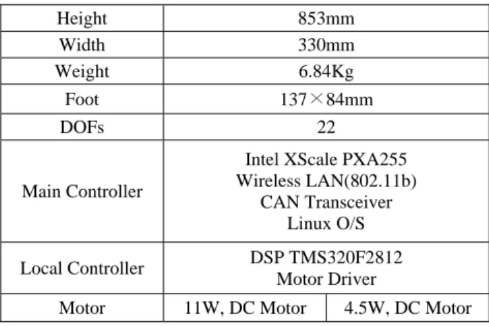
A humanoid robot is presented in Fig. 1 and its hardware specifications described in Table 1. It had 22 DOFs, which are 6 in each leg, 3 in each arm, 2 in main body and 2 in head. Each joint consists of two kinds of motors, 4.5watt and 11watt, and bevel gear reduction units, 190:1 and 231:1 respectively. It had 85.3 cm in height and it weighs 6.84 kg. Every joint has own control units to drive the actuator, to acquire data of sensors and to communicate with main controller.
Table 1 ISHURO Humanoid robot specifications
Height 853mm Width 330mm Weight 6.84Kg Foot 137×84mm DOFs 22 Main Controller
Intel XScale PXA255 Wireless LAN(802.11b)
CAN Transceiver Linux O/S
Local Controller DSP TMS320F2812
Motor Driver
Motor 11W, DC Motor 4.5W, DC Motor
ZMP Compensation Algorithm for Stable Posture of a Humanoid Robot
Byung-Hun Hwang*, Jung-Shik Kong
**, Bo-Hee Lee
***,
Jin-Geol Kim
****and Uk-Youl Huh
******School of Electrical Engineering, Inha University, Inchen, South Korea (Tel : +82-32-860-7384; E-mail: [email protected])
**Department of Automation Engineering, Inha University, Inchen, South Korea (Tel : +82-32-860-7384; E-mail: [email protected])
***Department of Electrical Engineering, Semyung University, Chechon, Korea (Tel : +82-43-649-1305; Email : [email protected])
****School of Electrical Engineering, Inha University, Inchen, South Korea (Tel : +82-32-860-7384; E-mail : [email protected])
*****School of Electrical Engineering, Inha University, Inchen, South Korea (Tel : +82-32-860-7384; E-mail : [email protected])
Abstract : The desired ZMP is different from the actual ZMP of a humanoid robot during actual walking and stand upright. A humanoid robot must maintain its stable posture although external force is given to the robot. A humanoid robot can know its stability with ZMP. Actual ZMP may be moved out of the foot-print polygons by external disturbance or uneven ground surfaces. If the position of ZMP moves out of stable region, the stability can not be guaranteed. Therefore, The control of the ZMP is necessary. In this paper, ZMP control algorithm is proposed. Herein, the ZMP control uses difference between desired ZMP and actual ZMP. The proposed algorithm gives reaction moment with ankle joint when external force is supplied. 3D simulator shows motion of a humanoid robot and calculated data.
Keywords: ZMP Compensation, ZMP Feedback, Stable Posture, Humanoid, ISHURO
ICCAS2005 June 2-5, KINTEX, Gyeonggi-Do, Korea
XBase YBase ZBase XRL0 ZRL0 YRL0 XRL2 ZRL1 YRL1 XRL1 ZRL2 YRL2 XRL3 ZRL3 YRL3 XRL4 ZRL4 YRL4 XLLT ZLLT YLLT XRL5 ZRL5 YRL5 XRL6 ZRL6 YRL6 XRL7 ZRL7 YRL7 XRLT,B ZRLT,B YRLT,B XLL0 ZLL0 YLL0 XLL1 ZLL1 YLL1 XLL2 ZLL2 YLL2 XLL3 ZLL3 YLL3 XLL4 ZLL4 YLL4 XLL5 ZLL5 YLL5 XLL6 ZLL6 YLL6 XB0 ZB0 YB0 XRA0 ZRA0 YRA0 XB1 ZB1 YB1 XBT ZBT YBT XRAT ZRAT YRAT XRA2 ZRA2 YRA2 XRA1 ZRA1 YRA1 XRA3 ZRA3 YRA3 XLAT ZLAT YLAT XH0 ZH0 YH0 XH1 ZH1 YH1 XLA0 ZLA0 YLA0 XLA1 ZLA1 YLA1 XLA1 ZLA1 YLA1 XLA1 ZLA1 YLA1
Fig. 1 3D model and coordination of a humanoid robot In order to realize the distributed control, two kinds of communication protocol were applied. One was wireless LAN. It used to connect PC simulator with main controller in a body of the robot, and the other was CAN, employed to communicate main controller with joint controllers. Force sensors were mounted on the feet to measure the ground reaction force and then calculate actual ZMP position. A inclinometer was mounted at a robot trunk to measure the angle for balancing of a robot body.
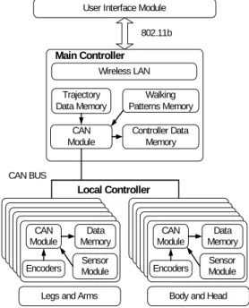
To realize the autonomous walking, a humanoid robot should have the modules: user interface, action, planner, vision and dynamics control of legs and arms as shown in Fig. 2. Wireless LAN Trajectory Data Memory Walking Patterns Memory Controller Data Memory CAN Module
User Interface Module 802.11b
CAN BUS
CAN Module
Encoders SensorModule Data Memory
CAN Module
Encoders ModuleSensor Data Memory
Legs and Arms Body and Head
Main Controller
Local Controller
Fig. 2 System Architecture
Since all controllers were connected through CAN network, the number of wire is significantly reduced with respect to the central architecture control system. The distributed controllers decreased in volume and weight lead to the reduction of energy consumption. So the distributed control architecture is
well suitable for the autonomous humanoid robot.
Main controller contains three different types of CPU. 32 -bit RISC CPU is used to control overall operation and its companion DSP processor is able to do fast computation in calculation of inverse kinematics and trajectory planning job, and also one CAN controller chip is mounted. Basically it has 64M SDRAM, additional memory can be extended using Multi Media Card. Host CPU and DSP use HPI (Host-Port Interface) protocol to transmit and receive data fast. To communicate with user interface module, main controller has wireless LAN, so user can send target position and data to a robot.
Local 32-bit DSP mounted control units have the ability to control their actuator. They also have the CAN module, A/D converter, PWM unit, and pulse encode unit, etc. Additionally it is equipped with interfacing circuit related with DC motor. The command data from main controller can be received through CAN and the local DSP controls its motor and sensors. Two or more local controller will have force sensors module and a inclinometer interface module.
3. ZMP CONTROL ALGORITHM
3.1 Walking Control Method
Fig. 3 shows that flow of walking control of a humanoid robot. All layers are implemented every unity gait cycle.
Fig. 3 Flow of walking control
When the goal position coordinate comes into gait planner, gait planner creates the gait path until goal position. Walking pattern generator creates the each step pattern. When the step pattern is decided, the trajectory generator makes the trajectory about one step to use inverse kinematics and then desired ZMP is to be calculated. Trajectory modifier does modification or regeneration of the trajectory using sensor feedback data every 10ms period.
3.2 ZMP Criterion
As we know that ZMP[6] is the element which is only in stability index verification of a humanoid robot. ZMP is the point where the resultant of the reaction force is applied. As long as the foot is in contact with the ground along its entire lower surface, the ZMP is inside the sole. Thus, locomotion is stable if the ZMP remains within the foot-print polygons.
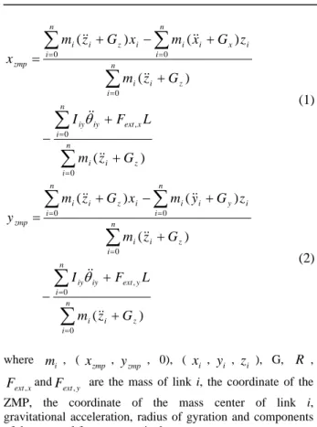
Eq. (1) and Eq. (2) are the ZMP equations[8] that are considered an external force.
ICCAS2005 June 2-5, KINTEX, Gyeonggi-Do, Korea
∑
∑
∑
∑
∑
= = = = =+
+
−
+
+
−
+
=
n i z i i n i x ext iy iy n i z i i n i n i i x i i i z i i zmpG
z
m
L
F
I
G
z
m
z
G
x
m
x
G
z
m
x
0 0 , 0 0 0)
(
)
(
)
(
)
(
&&
&&
&&
&&
&&
θ
(1)
∑
∑
∑
∑
∑
= = = = =+
+
−
+
+
−
+
=
n i z i i n i y ext iy iy n i z i i n i n i i y i i i z i i zmpG
z
m
L
F
I
G
z
m
z
G
y
m
x
G
z
m
y
0 0 , 0 0 0)
(
)
(
)
(
)
(
&&
&&
&&
&&
&&
θ
(2)
where i m , ( zmpx
, zmpy
, 0), (x
i ,y
i ,z
i ), G,R
, x extF
, andF
ext,y are the mass of link i, the coordinate of theZMP, the coordinate of the mass center of link i, gravitational acceleration, radius of gyration and components of the external force, respectively.
3.3 ZMP Feedback Control Algorithm
When a humanoid robot receives an external force, the robot system is unstable. And the actual ZMP get outside the stable region. Consequently, the actual ZMP must maintain within stable region. Here, stable region is space generated by contacting between the foot and the ground. Desired ZMP is calculated by pattern generator that is one of the robot system layers.
In fact, ZMP control is difficult with only using ZMP data. Most of all a humanoid robot makes use of various sensors for ZMP control. And a humanoid robot poses compensational motion in order to maintain stable posture. In this paper, ZMP is compensated by ankle joint.
Basic idea of ZMP feedback algorithm is to give a moment that is equal to external moment. We can measure the direction of external force by force sensor, but its magnitude is difficult to measure it. Motor at ankle actuate toward the opposite measured direction. Fig. 4 describes the ZMP feedback control.
Fig. 4 Block Diagram of the ZMP Feedback Control
4. SIMULATION AND RESULT
4.1 3D Simulator
The simulator GUI is shown in Fig. 5. This simulator is programmed with OpenGL and VC++. Each links has mass properties of a real humanoid robot. The simulator is able to perform kinematical interpretation, create a walking trajectory and simulate ZMP control.
Fig. 5 Simulator capture image 4.2 Control Simulation and Result
The simulation shows that actual ZMP is controlled by reaction moment. Here are 3 restricted conditions for simulation.
1. External force gives at less than 6.7N. If external force gives 6.7N or more force then robot is unstable.
2. The humanoid robot is always upright, and it does not walk.
3. Robot bodies are rigid and it has constant density. An external force data is shown in Fig. 6.
Fig. 6 external force data
Simulation result is shown in Fig. 7. Desired ZMP is zero. In view of the simulation result, the robot system output is satisfied. Compared to the other control methods[7], the proposed control method is quite simple. PID controller gains are heuristically.
ICCAS2005 June 2-5, KINTEX, Gyeonggi-Do, Korea
Fig. 7 Simulation result graph
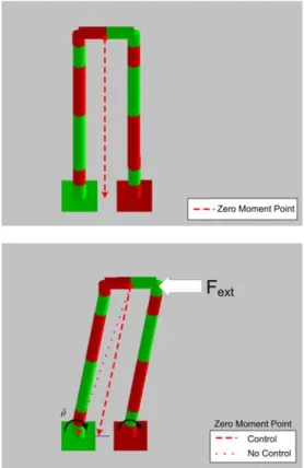
3D simulation result is shown in Fig. 8. If robot does not receive external force then robot is stable and ZMP is equal to COG(Center of Gravity). But, ZMP moves out of the stable region when external force gives to the robot. So, ankle joint actuate toward the opposite direction of external force. ZMP moves to zero point by PID controller.
Fig. 8 3D Motion by control
5. CONCLUSION
We presented a method to control ZMP for a humanoid robot. A humanoid robot requires various sensors for stable walking on uneven terrain or recognition of environments. Generally, humanoid robots are used Gyro-sensor, inclinometer, and accelerometer for stable posture or walking. The stability index of a humanoid robot can known with ZMP condition. If robot received an external force then ZMP moves out of stable region. So, robot requires ZMP control algorithm as well as sensors. In this paper, in order to realize the control
algorithm, built a 3D simulator. It simulates the instability which occurs by an external force. And realized ZMP control algorithm was verified with 3D simulator.
The future works are more detail environment parameters applied to this simulator and its performance verified experimentally.
ACKNOWLEDGMENTS
This work was supported by Grant No. R01-2003-000-10364-0 from Korea Science & Engineering Foundation.
REFERENCES
[1] Kazuo Hirai, Masato Hirose, Yuji Haikawa and Toru Takenaka, "The development of Honda Humanoid Robot," IEEE International Conference on Robotics &
Automation, pp. 1321-1326, 1998.
[2] Masahiro Fujita, Yoshihiro Kuroki, Tatsuzo Ishida and Toshi T. Doi, "Autonomous Behavior Control Architecture of Entertainment Humanoid," IEEE
Internation Conference on Intelligent Robots and systems, pp. 960-967, 2003.
[3] Koichi Nishiwaki, Satoshi Kagami, James J. Kuffer, Masayuki Inaba and Hirochica Inoue, "Humanoid 'JSK-H7' : Research platform for autonomous Behavior and Whole Body Motion," Internation Workshop on
Humanoid and Human Friendly Robotics, 2002.
[4] K. Loffler, M. Gienger and F. Pfeiffer, "Sensor and Control Design of a Dynamically Stable Biped Robot,"
IEEE International Conference on Robotics & Automation, pp. 484-490, 2003
[5] Jung-Hoon Kim and Jun-Ho Oh, "Walking Control of the Humanoid Platform KHR-1 based on Torque Feedback Control," IEEE International Conference on Robotics &
Automation, pp. 623-628, 2004
[6] Miomir Vukobratovic and Branislav Borovac, "Zero Moment Point - Thirty Five Years of Its Life,"
International Journal of Humanoid Robtics, Vol. 1, No 1,
pp. 157-173, 2004
[7] Jun Song, K.H. Low and Weimiao Guo, "A simplified hybrid Force/Position Controller Method for The Walking Robots," Robotica, Vol. 17, pp. 583-589, 1999 [8] Qiang Huang, Kazuhito Yokoi, Shuuji Kajita, Kenji
Kaneko, Hirohiko Arai, Noriho Koyachi and Kazuo Tanie, "Planning Walking Patterns for a Biped Robot,"
IEEE Trans. Robotics and Automation, Vol. 17, No 3,
2001