1. INTRODUCTION
Mobile robot localization and mapping in unknown environments is a fundamental requirement for effective autonomous robotic navigation. A key issue in the practical implementation of localization and mapping schemes concerns how map information is gathered and effectively. Obstacle detection is essential to the development of 2-D environmental models for autonomous mobile robots. The pursuit of appropriate sensor technologies has been riddled with issues including cost, accuracy, susceptibility to interference and noise. Many different sensor technologies have been used to develop 2-D environmental models including ultrasonic, laser and infrared range-finders. Ultrasonic sensors are popular due to their low cost, small size, low power consumption.
However, ultrasonic range finders have several drawbacks including low angular resolution, show data collection rate about the azimuth, secular reflection, sensitivity to changes in temperature and humidity, and relatively low accuracy in distance measurements compared to their laser counterparts. In addition, their annoying clicking sound when operation makes them less attractive for practical applications that involves a human user. In addition to the uncertainty in distance measurement, the ultrasonic transducer’s wide beam angle (30° for the popular Polaroid ultra sonic range finders [1]) results in greater uncertainty in the width of detected obstacle. 2-D laser scanners, on the other hand, have been widely used and studied for applications including object following and obstacle avoidance feature extraction, map building, and self-localization [2]. Laser range-finders provide more accurate range data over a longer detection range with higher angular resolution but are more expensive, bulkier, and heavier than ultrasonic. There is a need for a cost-effective sensor that can be used in 2-D mapping for mobile robotics. In this paper, a range finder sensor module for indoor 2-D mapping has been developed and advanced Hough transformation for map building. The rest of this paper is as following. In chapter 2 and 3, PSD range finding sensor module is represented, and a filtering algorithm for reducing the signal noise of sensor is explained, respectively. For line based map building, an advanced Hough transformation and navigation algorithm is represented in chapter 4 and 5.
2. A DEVELOPMENT OF PSD SENSOR MODULE
For range finder sensor, optic PSD (position sensitive detector) sensor array module was developed. It is cost effective and has less influence in the color of the object for
using the photo triangulation method. Although more limited in range than sonar, the optical triangulation sensor has high bandwidth and does not suffer from cross-sensitivities that are more common in the sound domain.
Fig. 1.The principle of the distance detecting using optical PSD sensor
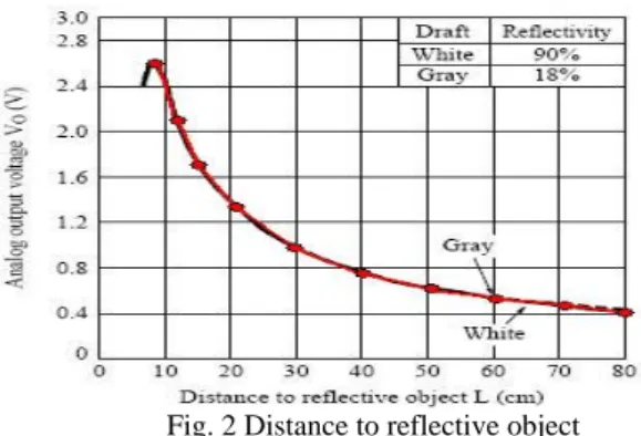
The principle of optical triangulation in PSD sensor is straightforward, as depicted in Figure 1. A collimated beam is transmitted toward the target. The reflected light is collected by a laser and projected onto a position-sensitive detector. Given the geometry of Figure 1, the distance D is given by
D = f·L/x, (1)
Therefore we found real distance information by using linear interpolation method.Fig. 2 Distance to reflective object
Figure 3 shows the layout of the proposed PSD sensor module. The PSD sensor module has 24 PSD sensors and each PSD sensor is allocated at interval of 15 degrees. The developed system consists of 16 bit RISC MPU, 6 analog MUX and RC Low Pass Filter. The sensor controller transfer scanned data to robot controller with RS232 communication. The sensor controller has 1Kbyte ring buffer to avoid the data loss problem owing to transmission speed. The moving
A development of PSD sensor system for navigation and map building
in the indoor environment
Tae Cheol Jeong*
,Chang Hwan Lee
**,Jea yong Park
***, Woong keun Hyun
**** Department of Electronics Engineering, Honam University, Gwangju, Korea (Tel : +82-62-940-5482; E-mail:*
[email protected], **[email protected] ,*** [email protected] ,**** [email protected])
Abstract This paper represents a development of a range finder sensor module for indoor 2-D mapping and modified Hough transformation for map building. A range finder sensor module has been developed by using optic PSD (Position Sensitive Detector) sensor array at a low price. While PSD sensor is cost effective and light weighting, it has switching noise and white noise. To remove these noises, we propose a heuristic filter. For line-based map building, also we proposed advanced Hough transformation and navigation algorithm. Some experiments were illustrated for the validity of the developed system.
velocity of robot for map building is decided by 20cm/sec. Therefore, PSD sensor module rescans the sensors at every 0.4cm moving distance. A sensor module scans the 24 sensors at every 20 msec.
Fig. 3 The allocation of PSD sensor array
A Figure 4 shows the system structure of the sensor module using a optical PSD sensor.
Fig. 4 A structure of the sensor module
3. FILTERING ALGORITHM
Fig. 5 switching noise pulse train
Fig. 6 switching noise signal before filtering
Figure 5 and figure 6 show switching noise and some white noise. As shown these figures, the magnitude of PSD switching noise is larger than that of white noise.
To remove the switching noise, we propose a heuristic notch filter and 3-point moving average filter. The frequency of switching noise is about 1KHz and the width is about 120μsec.
Fig. 7 The proposed filtering algorithm
Fig. 8 A algorithm structure of S/W filtering
Since scanning time for 24 channels is about 200μsec, sensor can detect the switching noise signal sequential scanning data. From observation this, we can remove the switching noise by following heuristic filtering method.
Step 1: For an i-th AD converting channel, find average values on n sequential sensor data.
Step 2: Select the larger value data than the average value Step 3: Find again the average value on the reminder data
except the selected data
Fig. 9 The output signal after filtering
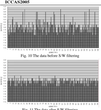
Figure 9 shows the sensor signal after heuristic filtering. Figure 10 shows the digitalized white noise signals converted with 8 bit binary resolution. For getting rid of these white noise, we adopted a 3-points moving average filtering algorithm to the averaged signals from heuristic filter. Figure 11 shows the resultant signal after the 3-points moving average filtering. As shown in figure 10 and figure 11, the magnitude of the noise is reduced as many as 4 times.
ADC 3-point moving average filter Sensor Heuristic Notch filter
Distance
Converter
Switching noise
White noise
Fig. 10 The data before S/W filtering
Fig. 11 The data after S/W filtering
4. ROBOT NAVIGATION ALGORITHM FOR
UNKNOWN ENVIRONMENT SCANNING
The navigation module is used to direct the robot to the destinations planned by the motion planner for unknown environment scanning. It uses the left and right clearances produced by the PSD sensor array.
For navigation of the robot, we assume that
(1) Robot can make two-wheel differential drive mode. (2) In 24 PSD sensors equipped in robot, only 8 sensors
are used as show in Fig12
(3) For navigation of unknown environment, the robot move to clockwise direction
The proposed algorithm refer next fuzzy inference engine. The linear velocity and the turning rate generated according to the fuzzy rule base are then sent to the control unit of the robot. The collision avoidance and navigation scheme comprises of 64 inference rules are in the form of:
If Si* is {F}, Si* + 1 is {F} and Si* + 3 is {C}
Then robot move to Si* direction, until the distance form Si* sensor is near to Dsafe. Rtr is ZE
Where Si* ={ F,M,N,C } Si*+1 = {F,M,N,C} Si*+3 = {F,M,N,C} Turning-rate ={VL,LE,ZE,RI,VR} • Si* : i-th Sensor
• Rtr : Turning rate of robot
The linguistic variables are defined as far(F), medium(M), near(N),close(C) turn very left (VL), turn left(LE), turn zero(ZE), turn right(RI), turn very right(VR) and Dsafe is safe distance between robot and wall.
Fig. 12 An exemplary result of navigation module The navigation module tracks the position and the orientation of the robot while the collision avoidance and navigation module controls the motion of the robot. These modules carry out their tasks under the direction of the motion planner. The motion planner generates motions by repeatedly specifying destinations and the directions of the destinations relative to the heading of the robots as one of the inputs of the fuzzy inference engine. Figure 13 shows the state diagram of the motion planner. It first tries to find the boundary of the area to be scanned. When a new object is found, the following object states are entered again and afterwards, the scan data for map building is updated. The operation will stop when the robot meets a goal position of which initial position is attached the wall. Firstly, robot finds initial position attached to the wall and follows the wall with clockwise direction. If the robot meets a dead reckoning state, it turns and moves to the moving clockwise state. This process keeps going until the robot meets goal position.
Fig. 13 The state diagram of the navigation and map building module
5. LINE-BASED MAP BUILDING ALGORITHM
Hough transformation can be used to detect simple geometry feature such as lines, circle, ellipses, etc.
Since scanned data from PSD sensor module represents a position in 2D space, we can find line segments for map buildings by using Hough transformation. For convenience of solution, line equations in 2D Cartesian space are described as figure 14 in parameter space (
ρ
,θ
)..
Fig. 14 A line equation expressed in
ρ
,θ
domainOne of the simplest geometrical primitives is the line segment. After obtaining scan data from navigation module, line segments for constructing the environment are determined by advanced Hough transform as follows.
For scan data
s
x
y
k
n
k k
k
(
,
),
=
1
,
2
,...,
STEP 1: Generating Hough transform domain. STEP 2:
(1) Finding quantized cells in which the number is over
ε
nin Hough domain.
(2) Removing the cells if the number of Hough transformation is smaller than near cells in a window in the set of selected cells.
STEP 3: Finding a minimum and a maximum position in the selected cells of STEP 2.
STEP 4: Removing the isolated scan data
Step 4.1: Finding distance between sorted scan data as minimum position.
Step 4.2: Removing a minimum scan data if its distance is larger than average value of the other distances as many as
ξ
n
times.
In STEP 3, the scan data in a cell represent positions in a line segment. Therefore the line segment can be found simply by connecting the minimum and maximum position data. Fig. 15 shows an isolated scan data
0
s
where 0s
,...,k
s
are included in the same cell in Hough domain. In the distance between the data, the distance of the isolated scan data is larger than the other's distance.ε
n and
ξ
n in STEP 2and STEP 4.2 are 65 and 10, respectively.
Fig. 15 There is the case when scanned data and isolated data are in the same cell of Hough domain.
6. EXPERIMENTS
Fig. 16 (a) The result of Map-building (b) Scan data in Hough domain
The exemplary map is a polygon which has 6 line segments. Figure 16 (a) shows the result of map building after adapting the proposed advanced Hough transformation. As shown in figure 16, our proposed method selects 6 lines segments and the built line based map is similar to the original polygon. Figure 16 (b) shows the scanned data in Hough transformation points which represent the information about the selected line segments as
ρ
andθ
. Whereρ
andθ
are angle and distance between origin point and sensed data points, respectively. Figure 16 shows a test bed example map and the result from proposed map building module processing. In Hough transformation, resolution is 1 degree inθ
and 1/300 of whole workspace inρ
.Fig. 17 A developed sensor module
Figure 17 shows the developed range finding sensor module with PSD sensors.
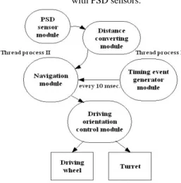
Fig. 18 The state diagram for driving mobile robot. A process for driving a robot has 5 S/W modules. Among them, navigation module and timing event generator module
run as thread processing. Timing event generator sends a signal at every 10 msec to navigation module. At this time, navigation module receives scanned data from distance converting module. Distance converting module converts the distorted scanned data to the real distance information from PSD sensor module.
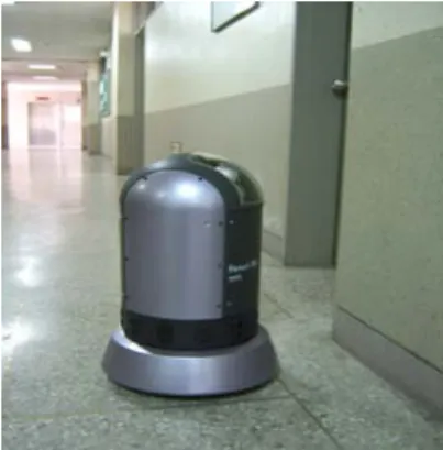
Fig. 19 The picture of working mobile robot. The mobile robot used for experiment is a differential driving type robot (Hanuri-RD). It has 3 driving motors for driving and rotating infinitely the body. The MPU of main controller is Strong ARM SA1110 and it communications with the peripheral devices with USB and RS232. The peripheral devices consist of ultrasonic transducers, CCD camera and PSD sensor module. The operating system is Embedded Linux (kernel 2.4.19-rmk7).
7. CONCLUSIONS
A range finder sensor module using low cost PSD sensor array has been developed. For the line based map building, advanced Hough transformation and navigation algorithm were proposed. The signal output of PSD sensor has uncertainty which consists of large switching noise and white noise. A heuristic filtering algorithm was also proposed to reduce these uncertain signals.
REFERENCES
[1] Data sheets for the Polaroid Ultrasonic Range-Finders, Polaroid Corporation.
[2] Cang Ye, Johann Borenstein, “Characterization of a 2-D Laser Scanner for Mobile Robot Obstacle Negotiation”, Proc. IEEE Int. Conf. On Robotics and Automation, Washington, D.C, December, pp. 2512-2518,2002 [3] L.luckiger, "A robot interfacing using virtual reality and
automatic kinematics generator," proc. of 29th Intl. Symposium on Robotics, pp. 123-126,1998.
[4] E.Nntonek and L.luckiger," irtual reality: an intuitive approach to robotics," SPIE, Vol. 2, pp 206-269, ?
[5] G.Dissanayake and H. Durrant-Whyte," A computationally efficient solution to the simultaneous localization and map building problem," ICRA'2000 Workshop on Mobile Navigation and mapping , 2000. [6] J.forsberg, U.Larsson, and A.Wernersson," Mobile robot
navigation using range-weighted hough transform," IEEE robotics and Automation Magazine, pp18-26, march 1995.
[7] R.madhavan, H.Durrant-Whyte, and G.Dissanayake," Natural landmark-based autonomous navigation using
curvature scale space," proc. of IEEE Int. Conf. on robotics and automation, 2002.
[8] K.S.Kim, S.J.Kim. and M.H. Choi, , “Virtual Robot Simulator and Real-World Robot Interface" Proceedings of the 12th KACC, October 1997. pp. 976-979.
[9] S.S.See, J.S.Oh, Y.H.Choi and J.B.Park "A New Complete Coverage Navigation Algorithm of Autonomous Cleaning Robot in Unknown Environment," KIEE/IEEK/ICASE Journal of Joint Conference, Vol. 1,pp. 33-36, May. 2001.
[10] Gonzales J., Ollero A., “Map Building for a Mobile Robot with a 2D Laser Rangefinder”, Int. Conf. Rob. & Autom., 1994, 1904-1909.
[11] Fortarezza G., Oriolo G., Ulivi G., Vendittelli M., “A mobile robot localization method for incremented map building and navigation”, Proc. of the 3rd Int. Symp. In Intell. Robotic Systems, 1995, 57-65.