This content has been downloaded from IOPscience. Please scroll down to see the full text.
Download details:
IP Address: 203.255.172.21
This content was downloaded on 03/11/2016 at 05:14
Please note that terms and conditions apply.
You may also be interested in:
Low Frequency Vibration Energy Harvester Using Spherical Permanent Magnet with Non-uniform Mass Distribution
Y Choi, S Ju, S H Chae et al.
Electromagnetic Vibration Energy Harvester Using Springless Proof Mass and Ferrofluid as a Lubricant
S H Chae, S Ju, Y Choi et al.
A low frequency vibration energy harvester using magnetoelectric laminate composite Suna Ju, Song Hee Chae, Yunhee Choi et al.
Low-frequency vibration energy harvester using a spherical permanent magnet with controlled mass distribution
Yunhee Choi, Suna Ju, Song Hee Chae et al.
A handy-motion driven, frequency up-converted hybrid vibration energy harvester using PZT bimorph and nonmagnetic ball
M A Halim, H O Cho and J Y Park
A magnetic-spring-based, low-frequency-vibration energy harvester comprising a dual Halbach array M Salauddin, M A Halim and J Y Park
Frequency Up-Converted Low Frequency Vibration Energy Harvester Using Trampoline Effect
View the table of contents for this issue, or go to the journal homepage for more 2013 J. Phys.: Conf. Ser. 476 012089
(http://iopscience.iop.org/1742-6596/476/1/012089)
Frequency Up-Converted Low Frequency Vibration Energy
Harvester Using Trampoline Effect
S Ju1, S H Chae1, Y Choi1, S Jun1, S M Park1, S Lee1, H W Lee2, and C-H Ji1
1
Department of Electronics Engineering, Ewha Womans University, Seoul, Korea
2
Department of Neurology, Ewha Womans University School of Medicine, Seoul, Korea
E-mail: [email protected]
Abstract. This paper presents a non-resonant vibration energy harvester based on
magnetoelectric transduction mechanism and mechanical frequency up-conversion using trampoline effect. The harvester utilizes a freely movable spherical permanent magnet which bounces off the aluminum springs integrated at both ends of the cavity, achieving frequency up-conversion from low frequency input vibration. Moreover, bonding method of magnetoelectric laminate composite has been optimized to provide higher strain to piezoelectric material and thus obtain a higher output voltage. A proof-of-concept energy harvesting device has been fabricated and tested. Maximum open-circuit voltage of 11.2V has been obtained and output power of 0.57μW has been achieved for a 50kΩ load, when the fabricated energy harvester was hand-shaken.
1. Introduction
Harvesting energy from environmental vibration is being widely researched to replace the conventional energy sources for emerging sensor applications [1]. Vibration energy harvester converts ambient mechanical vibration energy into electrical energy using piezoelectric, electromagnetic, and electrostatic transduction mechanisms. Magnetoelectric laminate composites based on magnetostrictive and piezoelectric materials are also investigated as a candidate for vibration energy harvesting [2]. Magnetoelectric harvesters can produce relatively higher output voltage without mechanical impact or frequency matching due to high strain generating capability of some of the magnetostrictive materials.
Generating power from low frequency vibrations such as human-body-induced motion poses a significant challenge due to its random nature, very low input frequency, and high acceleration. In general, conventional vibration energy harvester produces power using spring-mass-damper-based resonant system, which is optimized to operate at relatively narrow frequency band near the resonance. To overcome the well-known issues of conventional systems, wide variety of alternative approaches have been reported including the implementation of multi-frequency generator, resonant frequency tuning, utilization of impact-based piezoelectric generators and frequency up-converted electromagnetic transducers [3-5].
Despite the successful deployment in magnetic and piezoelectric energy harvesters, frequency up-conversion of magnetoelectric energy harvester has not been demonstrated. Previously, we have presented a non-resonant low frequency vibration energy harvesting device based on magnetoelectric laminate composite to generate power from random vibration of the ball magnet inside a channel [6].
PowerMEMS 2013 IOP Publishing
Although a high peak-to-peak voltage in response to various input vibrations has been observed, output power has been limited due to fast decay in output voltage and low input frequency. In this research, we present a magnetoelectric energy harvester based on mechanical frequency up-conversion using trampoline effect of aluminum springs integrated on both ends of the channel.
2. Harvester design
A schematic diagram of the proposed vibration energy harvester is shown in figure 1. The harvester consists of a spherical permanent magnet, a magnetoelectric laminate composite fabricated by stacking two MSMA (Magnetic Shape Memory Alloy) bars on top and bottom of an MFC (Macro Fiber Composite) sheet, and aluminum housing with monolithically integrated aluminum springs. The springless spherical permanent magnet inside a 25mm-long rectangular channel provides a time-varying vertical magnetic field to the magnetoelectric composite for power generation. When the magnet reaches the end of the channel, it bounces off the springs formed monolithically on the channel end. Spring constant of the S-shaped spring is 37.7kN/m. Teflon sheet covers the bottom of the channel to reduce the friction. Optimized gap between the ball magnet and MSMA is 1.5mm.
Figure 1. Schematic of the proposed energy harvester using spherical permanent magnet, integrated spring on channel end, and MSMA/MFC/MSMA laminate structure.
2.1. Bonding method of magnetoelectric laminate composite
To maximize the strain in magnetoelectric laminate composed of MSMA and MFC at given magnetic field variation, we have tested various boundary conditions and bonding configurations of constituent components, as shown in figure 2. As summarized in Table 1, harvester with cantilever-type transducer which had two MSMA bars on top and bottom of the MFC sheet and bonding regions limited to both ends of the MSMA bar produced the highest output.
Figure 2. Schematic diagram of bonding methods of magnetoelectric laminate composite. Table 1. Comparison of open circuit voltage for various bonding methods and configurations (harvester is hand-shaken).
Bonding region Entire MSMA bar Both ends of the MSMA bar
Both ends and center of the MSMA bar MSMA on top Bridge [%] 36.5 12.5 38.5 Cantilever [%] 65.4 92.3 107.7 MSMA on top and bottom
Bridge [%] 52.9 28.8 50
Cantilever [%] 100 156.9 113.5
PowerMEMS 2013 IOP Publishing
Journal of Physics: Conference Series 476 (2013) 012089 doi:10.1088/1742-6596/476/1/012089
2.2. Trampoline effect
The trampoline effect refers to definite elasticity in the impacting object such as baseball bat, tennis racquet, and golf club which act like a trampoline. This phenomenon means that the stored energy of impacting object is efficiently returned to the moving mass due to reduced energy dissipation during collisions. In this research, trampoline effect has been utilized to effectively return the stored compressional energy in the housing during the impact between the ball magnet and channel ends. In place of the flat channel ends used in the previous work [6], S-shaped aluminum spring has been formed on both ends of the channel for improved coefficient of restitution.
3. Fabrication
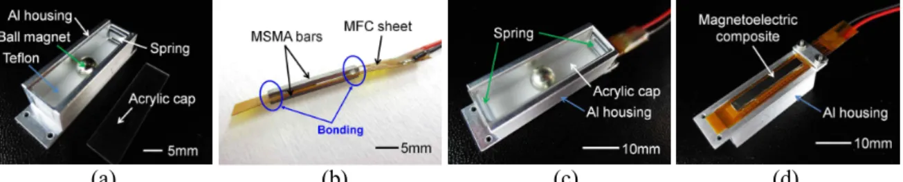
Figure 3 shows the fabricated energy harvesting device. A proof-of-concept harvester has been fabricated by assembling a 5mm-diameter NdFeB spherical magnet, a magnetoelectric component using MSMA/MFC/MSMA laminate structure, and aluminum housing with Teflon floor. Two MSMA bars (20x2.5x1mm3) have been attached to an MFC sheet (36x5.6x0.3mm3) with limited bonding region on both ends of the MSMA elements. Magnetoelectric laminate has been fixed to the housing in cantilever configuration using miniature screws. Effective volume of the assembled device measures 26x9x8.5mm3.
(a) (b) (c) (d)
Figure 3. Assembled device: (a) aluminum housing with spherical permanent magnet and Teflon plate at the bottom, (b) MSMA/MFC/MSMA laminate composite, (c) top-side of the energy harvester, (d) bottom-side of the energy harvester.
4. Results and discussion
Fabricated device has been tested using vibration exciter. Output from the harvester has been measured at 6-20Hz sinusoidal excitation with 1Hz step. Input acceleration at each frequency has been varied from 1g to 3g with 0.5g step. Input vibrations at frequencies under 6Hz and accelerations larger than 3g could not be applied due to the limitation of the exciter. In addition, manual vibration test has been carried out where the fabricated device has been attached to the backside of a smartphone and output has been measured when the phone was hand-shaken.
4.1. Vibration exciter test
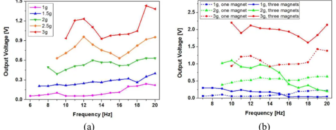
Device with single magnet and with three magnets connected in series have been tested and compared. In addition to the change in magnetic field distribution and total mass, increased number of magnets effectively increases the length of the proof mass, thereby reducing the time required for the magnets to impact the channel end.
As shown in figure 4, peak-to-peak open-circuit voltage showed an increasing trend as the acceleration was increased in both cases, with very weak frequency dependence. In addition, increase in output voltage was pronounced for device with three magnets at higher input accelerations, although responses to frequencies higher than 16Hz require further investigation (figure 4(b)). Maximum open-circuit voltage of 1.43V has been obtained at 19Hz for device with single magnet, and 2.2V has been obtained at 20Hz for device with three magnets.
As shown in figure 5(a), decay of the output waveform has been reduced substantially compared to previous results [6], presumably due to change in resonance mode affected by changed channel end geometry. Also, improved output voltage and increased number of visible peaks per cycle have been
PowerMEMS 2013 IOP Publishing
observed with the three-magnet device, which confirms the frequency-up-conversion effect (figure 5(b)). Frequency of impact between the magnet and channel end per each cycle of input vibration has been increased by a factor of 2 due to addition of springs on channel ends and increased length of the proof mass.
(a) (b)
Figure 4. Vibration exciter test results: (a) open-circuit voltage vs. frequency at various input accelerations (device with single magnet), (b) open-circuit voltage vs. frequency at various input accelerations at different number of magnets (device with single magnet and three magnets).
(a) (b)
Figure 5. Open-circuit voltage waveform for vibration exciter test: (a) device with single magnet (3g acceleration at 19Hz), (b) device with three magnets (3g acceleration at 20Hz).
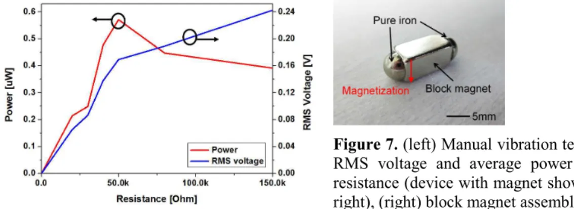
The RMS (root-mean-square) voltage and average power delivered to the external resistive load for device with three magnets are shown in figure 6. The maximum output power reached 0.045μW across a 50kΩ resistor when 3g acceleration at 20Hz has been applied. Average power of the device with three magnets is about 1.5 times higher than the power generated with device having single magnet.
Figure 6. Vibration exciter test results: RMS voltage and average power vs. load resistance for device with three magnets (3g acceleration at 20Hz has been applied).
PowerMEMS 2013 IOP Publishing
Journal of Physics: Conference Series 476 (2013) 012089 doi:10.1088/1742-6596/476/1/012089
4.2. Manual vibration test
For the manual vibration of device with three magnets, typical output voltage and average power were 5V and 0.35μW, respectively. To further improve the output by extending the total length of the magnet while maintaining the perpendicular magnetic field, modified device with block magnet (9.5x4.8x4.8mm3) and two hemispherical pure irons attached on both ends has been tested. Maximum open-circuit voltage of 11.2V and output power of 0.57μW have been achieved (figure 7).
Figure 7. (left) Manual vibration test results: RMS voltage and average power vs. load resistance (device with magnet shown on the right), (right) block magnet assembly.
For further improvement of the generated power, coefficient of restitution at both ends of the cavity, geometry of the proof mass and magnetizing direction of the magnet can be optimized. Moreover, electrode configuration of the MFC sheet requires further optimization.
5. Conclusion
We have demonstrated a non-resonant magnetoelectric vibration energy harvester based on mechanical frequency up-conversion of input vibration using trampoline effect of aluminum springs integrated on both ends of the channel. A proof-of-concept vibration energy harvester has been designed, fabricated, and tested successfully. For device with three magnets, maximum open-circuit voltage of 2.2V has been obtained at 3g acceleration at 20Hz. Moreover, maximum open-circuit voltage of 11.2V has been obtained and output power of 0.57μW has been achieved for a 50kΩ load, when the fabricated device with block magnet was mounted on a smartphone and shaken manually. Although the device requires further optimization to achieve higher output voltage, we have successfully demonstrated the feasibility of frequency up-conversion using trampoline effect.
6. Acknowledgement
This work was supported by the Ewha Global Top 5 Grant 2011 of Ewha Womans University and by the Pioneer Research Center Program through the National Research Foundation of Korea funded by the Ministry of Science, ICT & Future Planning (2010-0019453).
References
[1] Najafi K et al. 2011 Microsystems for energy harvesting Proc. Transducers 2011 (Beijing, 5-9
June 2011) 1845-1850
[2] Beeby S P et al. 2006 Energy harvesting vibration sources for microsystems applications Meas.
Sci. Technol. 17 175-195
[3] Ashraf K et al. 2013 Improved energy harvesting from low frequency vibrations by resonance amplification at multiple frequencies Sens. and Act. A 195 123-132
[4] Gu L et al. 2011 Impact-driven, frequency up-converting coupled vibration energy harvesting device for low frequency operation Smart Mater. Struct. 20 045004
[5] Galchev T et al. 2011 Micro power generator for harvesting low-frequency and nonperiodic vibrations J. Microelectromech. Syst. 20 852-866
[6] Ju S et al. 2013 Harvesting energy from low frequency vibration using MSMA/MFC laminate composite Proc. Transducers 2013 (Barcelona, 16-20 June 2013) 1348-1351
PowerMEMS 2013 IOP Publishing