P1-101 / M. Okumura
IMID 2009 DIGEST •
Abstract
The authors have developed the display system which can be viewed from any direction. In this paper, we propose an omni-directional 3D display system for cooperative activity on a round table.
1. Introduction
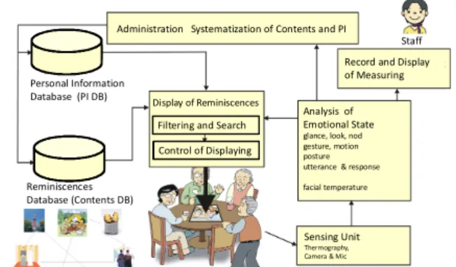
The authors have researched multimedia system and support system for nursing studies on and practices of reminiscence therapy and life review therapy. The concept of the life review is presented by Butler in 1963. The process of thinking back on one's life and communicating about one's life to another person is called life review. A therapist must keep a record of sessions for inspection of methods and ways of valuation on reminiscence and life review therapy, but it is trouble for the therapist to record. The aim of research is to develop the support system which can automatically give an optimum topic and write down a session report about the activity. This life review is often assisted by aids such as videos, pictures, objects, archives and life story books, as shown in Fig. 1, in order to make an opportunity of talking. We want to develop an omni-directional display system for cooperative activity on a round table to enable all-around viewing and unification of media contents by an electronic form.
2. Motivations
This paper describes an omni-directional display system that can be viewed from any direction (i.e., the display has four viewing zones so as to perceive a screen view of the display at all directions around a table). The authors have ever researched information display systems involving 3D imaging1)2)3). However,
a conventional monitor display is viewed from one direction, that is, the display has narrow viewing angle and observers cannot view the screen from the opposite side. Hence we developed a tabletop display system for collaborative tasks cooperated by four users4 ). This tabletop display can provide different images to four users surrounding the system utilizing an optical grating film for generating a virtual screen and floating above the top level of an actual display panel. The floating virtual screens of this display are generated into a square pyramid in front of observers’ eyes. But this system can display only 2D views which are viewed correctly by all users from any direction. Then this paper describes an omni-directional 3D display system for the all-around viewing.
Personal Information Database (PI DB)
Reminiscences Database (Contents DB)
Administration Systematization of Contents and PI
Display of Reminiscences Filtering and Search Control of Displaying
Sensing Unit
Thermography, Camera & Mic
Record and Display of Measuring
Staff
Analysis of Emotional State
glance, look, nod gesture, motion posture utterance & response facial temperature
Fig. 1. Cooperative work of life review activity.
3. Principle
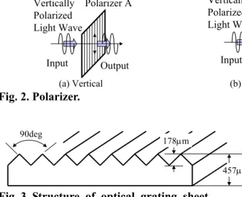
There are two types of polarizing filters, polarizers for short: linear and circular. Fig. 2 shows the basic concept of polarization using the linear polarizer. In this example, the linearly polarized incident light is vibrating vertically before encountering the polarizer,
Omni-directional 3D Display System
for Collaborative Work on Round Table
Mitsuru Okumura
1, Kunio Sakamoto
1, Shusaku Nomura
2,
Tetsuya Hirotomi
3, Kuninori Shiwaku
3and Masahito Hirakawa
31Konan University, 8-9-1 Okamoto, Higashinada, Kobe 658-8501, Japan e-mail: [email protected]
2Nagaoka University of Technology, 1603-1 Kamitomioka, Nagaoka 940-2188, Japan
3
Shimane University, 1060 Nishikawatsu-cho, Matsue, Shimane 690-8504, Japan
P1-101 / M. Okumura
• IMID 2009 DIGEST
a filter containing long-chain polymer molecules that are oriented in a single direction. Only the incident light that is vibrating parallel to the polarization direction is allowed to pass. Therefore, since polarizer A is oriented vertically, it only permits the vertical waves in the incident beam to pass. However, the vertically polarized waves are subsequently blocked by polarizer B because it is oriented horizontally and absorbs all of the waves that reach it due to their vertical orientation. Polarizer A Input Output Vertically Polarized Light Wave (a) Vertical Polarizer B Input Vertically Polarized Light Wave (b) Horizontal Fig. 2. Polarizer. 90deg 457µm 178µm
Fig. 3. Structure of optical grating sheet.
The authors found an interesting material at Tokyu Hands in Shinjuku, Tokyo, Japan. Tokyu Hands is one of the more interesting Do-It-Yourself type stores in Japan. There are many interesting gadgets, gifts, hobby or craft items you might want. The item, which we found, is the optical film and it is named “SOLF”. The SOLF optical sheet is a flexible film with prisms designed to transport and diffuse the light. This prism sheet diffracts two beams. These beams are called as the first order diffracted beam and the second order diffracted beam.
Fig. 3 shows the structure of the optical grating sheet. A grating diffracts or scatters a light beam with a designed angle. This sheet has interesting characteristics as follows; the prismatic phenomenon is observed and the doubling can be visible through the sheet like the Calcite. This doubling phenomenon occurs because the prism sheet diffracts two beams. This sheet provides us with a doubling image as shown in Fig. 4. Using this characteristic, the authors shift the images for displaying virtual images of LCD displays at different space from original positions by adjusting the interval between an
optical sheet and an image plane of the LCD panel.
Fig. 4. Doubling phenomenon.
f f
Image Object
dO dI
Fig. 5. Lens optics for generating real image.
4. Conventional 4-views Display
The convex lens serves to direct each image into the specific direction. This image generation of the convex lens is also based on this principle as shown in Fig 5. Real images occur when objects are placed outside the focal length of a converging lens. A real image is illustrated in Fig 5. Ray tracing gives the position of the images by drawing one ray perpendicular to the lens, which must pass through the focal point, and a second ray that passes through the center of the lens, which is not bent by the lens. The intersection of the two rays gives the position of the image. A third ray could be drawn which passes through the focal point on the left side of the lens; after passing through the lens, it would travel parallel to the axis, and would intersect the other two rays at the point where those rays already intersect. Note that the real image is inverted. The position of the image can be found through the equation:
1/dO + 1/dI = 1/f
Here, the distances are those of the object and image respectively as measured from the lens. The focal length f is positive for a convex lens. A positive image distance corresponds to a real image, just as it did for the case of the mirrors. However, for a lens, a positive image distance implies that the image is located on the opposite side from the object.
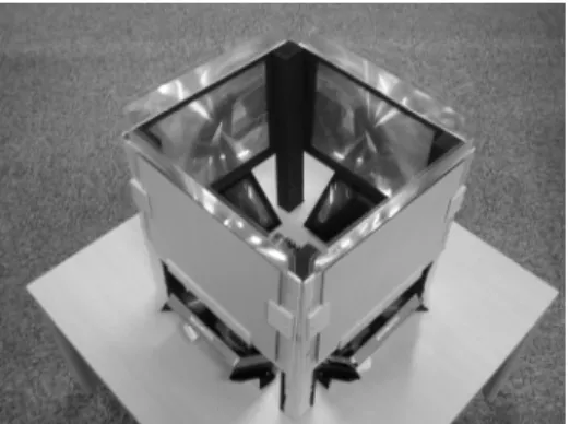
Fig. 6 shows the appearance of a floating display system. This display consists of four LCD panels, convex lenses and mirrors. A pair of display and lens generates a floating image in front of a lens. To
P1-101 / M. Okumura
IMID 2009 DIGEST • simplify an optical layout, the mirrors are attached on
the lenses. This mirror reflecting can downsize the display unit. In the prototype display, the interval of the display and the lens is 400 mm. The floating images are generated about 350 mm apart from the lens. Since this display has four image units, observers can perceive four different images from corresponding directions around the table.
Fig. 6. Tabletop display system(KNX-35).
5. 4-views 3D Display Units
To enable all-around viewing from four directions, it is necessary to generate a virtual 3D screen. So this 3D viewscreen is floating above and sinking below the top or under level of an actual display panel as shown in Fig. 7. To simplify an optical layout, the authors utilize a grating sheet for locating pseudo images at different places from original positions. As shown in Fig. 8, the grating sheet provides a diffracted image which is arranged under or above original position. The grating sheet diffracts or scatters a light beam with a designed angle. This interesting phenomenon reminds us of method to shift image positions by a simple optical layout.
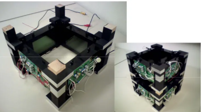
As shown in fig. 7, our developed omni directional 3D display system consists of eight LCD panels, an optical grating film for overlapping stereoscopic images and orthogonal polarizaers for separating left and right images. Fig. 9(a) shows a display unit and its layout constituted of four panels. This unit produces a left or right image of 3D view. To show left and right images, two display units are piled as shown in Fig. 9(b). Fig 10 shows the appearance of our developed prototype display. An LCD display produces their image by having a liquid crystal layer that when a current runs through the pixel, it turns on that shade of color. The problem with the liquid crystal is that this color can only be accurately represented when viewed straight on. The
further away from a perpendicular viewing angle, the color will tend to wash out. Thus, LCD displays have a limited viewing angle. As an observer watches a viewing screen on the panel with overlooking through the grating sheet, it loses contrast and becomes hard to read at out of the viewing angle as shown in fig. 11(a). The snapshot of fig. 11(a) is taken from upward diagonal direction. To correct visual clarity of an LCD’s viewing screen, the LCD panels are covered with the grating sheet because a grating diffracts a ray into upwards and downwards. Although the snapshot of fig. 11(b) is taken from upwards at same angle, it has more contrast and is easier to read at out of the viewing angle using the grating sheet. Polarizer Grating sheet Virtual screen Polarizer Polarizer Display panel Display panel
(a) side view
Display panel Polarizer Grating sheet Polarizer Polarizer Grating sheet (b) top view Fig. 7. Optical layout of 3D display(KNA-10).
Fig. 8. Grating sheet.
As shown in fig. 7, two display panels are arrayed vertically in order to produce left and right images. A grating film appropriately locates apart from the panels so as to shift both images into the same position for superimposing stereoscopic images by adjusting the interval between the optical sheet and the display panels. Orthogonal polarizers work as an image separater for delivering left and right images into appropriate eyes. The lights of an LCD pass through the polarizers or are blocked by the polarizers whether eyes are corresponding to each image or not. An observer can perceive the left and right image through polarizers which have the same direction of
Diffracted image Grating sheet 80mm 20mm 180mm Output beam Input beam
P1-101 / M. Okumura
• IMID 2009 DIGEST
polarization. Thus you can see the 3D image without special glasses.
(a) display module (b) piled module Fig. 9. Display unit.
Fig. 10. Appearance of omni-directional display.
(a) no grating sheet
(b) grating attached Fig. 11. Effect of grating sheet.
6. Current working model
We have developed the prototype display system using eight commercial LCD panels. These displays have a 5.4 inch LCD panel and its size is 108mm(W)
x 68mm(H). The video input supports NTSC. The panels are fixed on edges of a 250mm square. Each panel is covered with a 100mm square polarizer so as to separate left and right images into appropriate eyes. Moreover, a 100mm square grating sheet is attached on the panel in order to improve visual clarity. The size of viewing windows on surfaces of the box is 120mm(W) x 80mm(H). This viewing window is also covered with two orthogonal polarizers and a grating sheet. The interval between centers of two LCD panels, which are vertically arrayed, is 210mm. The distance between these LCD panels and the viewing window is approximately 220mm so as to overlap left and right images at the same position. Since a polarizer blocks a light with orthogonal polarization and diffrent polarizers are attached with dividing in half, an observer perceives an only virtual 3D screen right in front of his/her face without special glasses. Observers can watch the screen of a display from any direction because this system has four 3D screens with four viewing directions.
7. Acknowledgements
This research is partially supported by “Grant-in-Aid for Young Scientists(B)” #20700112 and “Scientific Research (C) (General)” #20500481 from Ministry of Education, Culture, Sports, Science and Technology Japan(MEXT) and also by a grant from the Hyogo Science and Technology Association. A part of this work is done while the author is partially supported by the Hirao Taro Foundation of the Konan University Association for Academic Research, Japan.
8. References
1. K. Sakamoto, H. Nakayama, S. Taneji, “Field-lens Display: Headtracking enables 3D image viewing at any position”, Advances in intelligent IT, Active Media Technology 2006, pp. 277-280, (2006). 2. K. Sakamoto, M. Takaki, M. Nishida, “Parallax
Barrier 3D Reflection Display Using Holographic Screen”, Proc. of 12th International Display Workshops, pp.1769-1772, (2005).
3. K. Sakamoto, R. Kimura, M. Takaki, “Elimination of Pseudoscopic Region of Parallax Barrier 3D Display”, Proc. of 11th International Display Workshops, pp. 1497-1498, (2004).
4. T. Yamanari, K. Sakamoto, S. Nomura, T. Hirotomi, K. Shiwakuand M. Hirakawa, “4-views Display System for Collaborative Work on Round Table,” Proc. IDW ’08, pp. 341-342 (2008).