669
-Abstract - In this paper, rotor design modification of a novel proposed machine termed the Axial Flux Doubly Fed Reluctance Machine (AF-BDFRM) is studied. The main potential advantage of AF-BDFRM is that it has larger torque and power density compared to radial flux-BDFRM. However, with the general rotor pole shape, this machine output back EMF has high THD % and high cogging torque. This paper studies the rotor design modification in the proposed AF-BDFRM to reduce the THD % in inducedd back EMF and cogging torque. Also the transient 3D finite element analysis (FEA) optimization of initial design is presented.1. Introduction
Brushless doubly fed reluctance machines (BDFRMs) are a class of machines that may be controlled using a power converter that has a rating lower than the total power rating of the machine. Doubly fed Reluctance machines are an attractive solution for applications where speed control over a limited operating range is required. One of the windings is connected directly to the power grid, while the secondary winding is connected through a power converter[1]. Schematic diagram of the operation is shown in the Fig. 1. Typically, the rating of the power converter is significantly smaller than the total power rating of the machine which lowers the cost of the overall system. The most well-known application of a doubly fed machine is probably the use of a doubly fed induction generator (DFIG) with a wind turbine. Need for slip rings to supply power to the rotor circuit in DFIG is a clear drawback, which may result in increased operating and maintenance cost [3]. Brushless doubly fed machines (BDFMs), also described in the literature as doubly fed brushless machines, are one alternative to the use of slip rings in DFIGs. The fundamental idea behind this type of machine is almost 100 years old and was further developed some 40 years ago but it has seen increasing interest in various forms over the last two decades [2].
The machine model proposed in this paper has two stators and one simple salient pole Reluctance rotor. In this paper, analysis of rotor pole shape modification of AF-BDFRM is studied and its transient 3D FEA is done using ANSYS MAXWELL software.
2. Proposed AF-BDFRM Model
AF-BDFRM configuration is shown in Fig. 2. it has two stators and one salient iron rotor. Rotor pole shape is modified form genral to improve the THD % and cogging torque [4]. Fig. 3. describes the rotor pole shape modification. this modification affects the ratio of direct and quadrature axis inductance ratio.
<Fig. 1> Schematic Design of BDFRM
(a)
(b)
<Fig. 2> Configuration of the proposed AF- BDFRM. (a) Full machine view
(b) Quarter model- detailed view
(a) (b) <Fig. 3> Rotor pole
(a) General shape (b) Modified shape
Table. 1. describes the design specifications of the proposed AF-BDFRM. Number of pole pairs of power and control windings is selected according to the requirement of the operational speed. synchronous speed at which control winding frequency goes to zero, is 300 rpm. Relationship among winding pole pairs and rotor saliencies is describes as: [3]
축방향 자속 이중 여자 방식의 이중 고정자를 갖는 릴럭턴스 기기의 회전자 설계
살만 칼리크*, Thomas Anthony Lipo**, 권병일*
한양대학교*, 플로리다 주립 대학교**
Axial Flux Dual Stator Doubly Fed Reluctance Machine Rotor design
Salman Khaliq*, Thomas Anthony Lipo**, Byung-il Kwon* Hanyang University*, Florida State University**
q
p
P
r=
±
670
-<TABLE I> Design specifications of the proposedAF-BDFRM 0 4 8 12 16 -2 -1 0 1 2 F lu x l in k a g e [ W b ] Tim e [ms]
General shape Modified shape
<Fig. 4> Flux linkage 3. Electromagnetic performance
Fig. 4. compares the flux linkages of the general rotor pole shape and the modified shape. it shows the the flux linkage has been reduced in the proposed shape. The reason behind that is the reduction of iron volume in the proposed shape which reduces the flux linkage capability from control winding to the power winding.
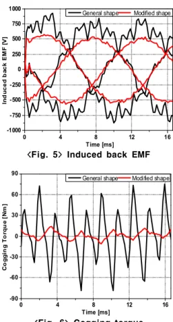
Fig. 5 compares the induced back EMF in the power winding when only control winding is excited. RMS value in the proposed shape has been reduced to 390 V from 530 V in the general shape. However, THD % which was about 19 % with the general shape of rotor pole, is reduced to 4.8 % with the modified shape.
Fig. 6. compares the cogging torque values of general and modified rotor pole shape. it can be seen that the cogging torque value is reduced to 26 Nm in the modified shape which was 154 Nm in the general shape. Which shows the huge advantage of the modified rotor pole shape.
It is very clear from the above analysis that the rotor pole shape plays a very important part in this proposed machine. Through the rotor pole shape modification, this machine has been able to be utilized in variable speed applications
0 4 8 12 16 -1000 -750 -500 -250 0 250 500 750 1000 In d u c e d b a c k E M F [ V ] Time [ms]
General shape Modified shape
<Fig. 5> Induced back EMF
0 4 8 12 16 -90 -60 -30 0 30 60 90 C o g g in g T o rq u e [ N m ] Time [ms]
General shape Modified shape
<Fig. 6> Cogging torque i.e. wind energy.
5. Conclusion
Rotor design of a new proposed AF-BDFRM is modified in this paper. Transient 3D FEA results reveal the large reduction in THD % of induced back EMF and cogging torque with this new rotor pole shape. However, the modified rotor pole contains lesser iron volume than the general shape rotor pole. This affects the flux linkage capability and induced back EMF. Further optimization will be done in future to find a good compromise among THD %, cogging torque and output back EMF.
This research was jointly supported by the "BK21PLUS program" through the National Research Foundation of Korea funded by the Ministry of Education and the "Human Resources Program" in Energy Technology of the Korea Institute of Energy Technology Evaluation and Planning (KETEP), granted financial resource from the Ministry of Trade, Industry and Energy, Republic of Korea. (20154030200730).
[References]
[1] A. M. Knight, R. E. Betz, D. G. Dorrel, "Design and Analysis of Brushless Doubly Fed Reluctance Machine," IEEE Tarns. On Ind. Appl. vol. 49, no. 1, Jan/Feb 2013.
[2] A. Broadway and L. Burbridge, “Self-cascaded machine: A low speed motor or a high frequency brushless alternator,” Proc. Inst. Elect. Eng.— Elect. Power Appl., vol. 117, no. 7, pp. 1277–1290, Jul. 1970.
[3] L. Xu, F. Liang, T. A. Lipo,. “Transient Model of a Doubly Excited Reluctance Motor,” IEEE Trans. On Energy Conversion, vol. 6 , no. 1, March 1991.
[4] Wenliang Zhao; Lipo, T.A.; Byung-Il Kwon, "Material-Efficient Permanent-Magnet Shape for Torque Pulsation Minimization in SPM Motors for Automotive Applications,"Industrial Electronics, IEEE Transactions on , vol.61, no.10, pp.5779,5787, Oct. 2014
Item Unit AF-BDFRM
Power winding pole pair - 4
Control winding pole pair - 8
Each air gap length mm 0.85
Di/Do - 3/5
No. of slots in upper and
lower stator - 96
Axial thickness of rotor mm 15 Surface current density/ stator
(peak) A/m 30000
No. of rotor saliencies - 12
No. of turns/ phase - 280
Rated current in control