ICCAS2005 June 2-5, KINTEX, Gyeonggi-Do, Korea
1. Introduction
Antiskid brake controllers have been in widespread use for many years. In the simplest sense, an antiskid brake controller compares the speed of vehicle (e.g., automobile, aircraft, etc.) derived from a wheel speed sensor to the vehicle speed derived from secondary or reference source. If wheel is determined to be skidding an excessive amount, then brake pressure applied to the wheel is released and the wheel is allowed to spin back up to appropriate speed. Antiskid brake controllers should provide consistently shorter stopping distance under all types of runway conditions. The essence of aircraft braking control is to continuously adjust brake pressure to maintain optimal braking torques. This optimum level should balance tire and runway friction at its peak value, yielding maximum braking deceleration. It influences not only the deceleration and the taxing distance of an aircraft, but also the strength and the fatigue life of the landing gear.
In this paper, an antiskid brake controller for a fixed-wing aircraft, which performs adaptive type proportional skid control, locked-wheel skid control and touchdown protection, is studied. The anti-skid control system of an aircraft is composed of two wheel speed sensors for sensing braking wheel speeds, a brake control unit (BCU) for control, and pressure control valve for the modulation of braking pressure on each wheel besides the conventional mechanical-hydraulic brake system.
As for the brake control unit, a Mark IV type - fully digital - brake controller is studied. For the development of its control algorithms, a 5-DOF (Degree of Freedom) aircraft landing model is composed in the form of matlab/simulink model at first. Then, braking moment control algorithms using wheel decelerations and slips are made. The developed algorithms are tested in software simulations using state-flow toolboxes
in matlab/simulink model. Also, a real-time simulation systems are made, which use hydraulic brake systems of a real aircraft, pressure control valves and its controller as hardware components of HIL(Hardware In-the-Loop) simulation. Algorithms tested in software simulations are coded into the controller and the real-time landing simulations are made in very severe road conditions. The real-time simulation results are presented.
2. Brake Controller for fixed-wing aircraft
In the conventional mechanical-hydraulic brake systems of fixed wing airplane, a master cylinder coverts the pilot’s pedal command to pressure for the input of metering valve. The metering valve boosts the master cylinder output pressure to the level of system pressure. So the braking pressure in each wheel is controlled by pilot’s pedal command. But no wheel signal feedback is made. But if wheel speed signals are feedback to brake controller and properly reduced braking pressure is applied to wheel, the wheel can experience no skidding. Fig. 1 is a schematic diagram of this type of antiskid brake control system.
Master Cylinder Master Cylinder Pressure IN Pressure Rtn BCU BRL P BRR P 1 V 2 V CMD I MCL P MCR P Pedal
Command ParkingBrake
Pressure Control Valve and Metering Valve
Fig. 1. Antiskid brake control system for a fixed wing aircraft
Development of Brake Controller for fixed-wing aircraft using hardware
In-the-Loop Simulation
Ki-Chang Lee*, Jeong-Woo Jeon*, Don-Ha Hwang*, and Yong-Joo Kim*
* Machine Control and Applications Group, Korea Electrotechnology Research Institute, Changwon, Korea (Tel : +82-55-280-1543; E-mail: leekc@keri.re.kr)
Abstract: Today, most fixed-wing aircrafts are equipped with the antiskid brake system. It can modulate braking moments in the
wheels optimally, when an aircraft is landing. So it can reduce landing distance and increase safeties. The antiskid brake system for an aircraft are mainly composed of braking moment modulators (hydraulic control valves) and brake control unit. In this paper, a Mark IV type - fully digital - brake controller is studied. For the development of its control algorithms, a 5-DOF (Degree of Freedom) aircraft landing model is composed in the form of matlab/simulink model at first. Then, braking moment control algorithms using wheel decelerations and slips are made. The developed algorithms are tested in software simulations using state-flow toolboxes in matlab/simulink model. Also, a real-time simulation systems are made, which use hydraulic brake systems of a real aircraft, pressure control valves and its controller as hardware components of HIL(Hardware In-the-Loop) simulation. Algorithms tested in software simulations are coded into the controller and the real-time landing simulations are made in very severe road conditions. The real-time simulation results are presented.
Keywords: Brake Control Unit, Real-time Simulation, RCP(Rapid Control Prototyping), HILS(Hardware In-the Loop Simulation)
ICCAS2005 June 2-5, KINTEX, Gyeonggi-Do, Korea
2.1. Antiskid Braking Components
The antiskid brake control system includes the WOW (Weight On Wheel) relay signals for the detection of landing mode of the aircraft, a brake control valve assembly, a brake and antiskid control unit, the left and right wheel speed sensors. Two master cylinders and the parking brake/antiskid switch are also included. The brake pressure transducer on the wheel can be ignored, if proper pressure estimation algorithms are used. The brake control valve assembly contains a left and right metering valve, the parking brake valve, two parking shuttle valves, the pre-brake restrictor valve, two check valves, and the brake control manifold.
2.2. Functions of antiskid brake controller
Normal control of the left or right brake is accomplish ed separately by applying toe force to left and right brake pedals on the rudder controls from either front or rear cr ew station. Each pedal provides input to the left or right master cylinder that generates hydraulic pressure (
p
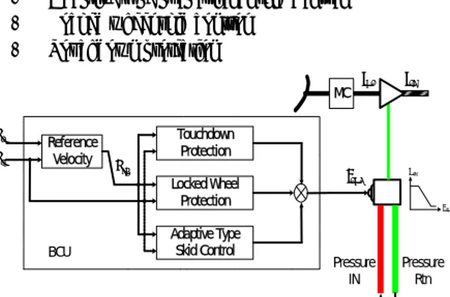
MC) p roportional to applied toe force (position). The master cyl inder pressure command is input to the antiskid control v alve metering valve section. The antiskid control unit pro vides a correction signal to the antiskid valve to reduce commanded brake pressure to the level that maintains opt imum wheel slip for maximum airplane deceleration, unde r all runway conditions. A functional schematic of the antiskid control system, which performs following functions, is presented in Fig. 2.- Adaptive type proportional skid control - Locked wheel skid control
- Touchdown protection Touchdown Protection Locked Wheel Protection Adaptive Type Skid Control 1 V 2 V Pressure IN Pressure Rtn BR P MC P MC CMD I CMD I BR P Reference Velocity REF V BCU
Fig. 2. Functions of Brake Control Unit (BCU) 2.2.1 Adaptive Type Skid Control
Adaptive type proportional skid control produces a brake pressure reduction by an amount proportional to the wheel’s skidding tendency. Wheel skidding tendency is the amount by which wheel slip exceeds the available peak slip value. After the wheel skid is corrected, brake pressure is reapplied. When the amount of pilot applied brake pressure is substantially greater than the amount needed to produce tire skidding, the adaptive feature causes an additional temporarily sustained pressure reduction so that less pressure is reapplied after the feature adjusts the skid detection threshold to closely match
the maximum wheel slip which can be produced without skidding. The proportional skid control for the right wheel operates completely independently of the proportional skid control for the left wheel.
2.2.2 Locked Wheel Protection
The locked wheel skid control feature operates on wheel speed only. When armed, a locked wheel detector causes brake pressure for its wheel to be fully removed whenever the speed of that wheel drops below 30% of aircraft velocity. The locked wheel protection will be armed for speed greater than 25 knots. Normal antiskid protection remains functional down to 10 knots.
For locked wheel skid control, the right and left wheel speeds are independently compared to a reference aircraft velocity. The reference aircraft velocity is provided by a memory circuit, which receives input signals from both right and left wheel speed sensors. Some conditions which cause the locked wheel skid control to operate are as follows: (1) when the aircraft lands in slightly banked attitude so that one wheel spins up before the other, locked wheel skid control sustains brake release on the non-rotating wheel after the touchdown feature is disengaged by the rotating wheel, (2) wheel unable to spin up because of hydroplaning on a flooded run way, or (3) brake seized so that it will not immediately release when pressure is reduced by normal skid control.
2.3. Touchdown Protection
The touchdown protection circuit prevents brake application before touchdown. Even if brake pedals are depressed, the brakes are fully released. The antiskid touchdown protection circuit is engaged to prevent brake application when both of the following conditions exist: (1) both left and right MLG weight on wheel switches are fully extended to airborne position (WOW switches indicate AIR mode), and (2) both wheel speed sensors are rotating at a speed less than that for 20 Knots The touchdown protection circuit is disengaged to allow brake application whenever either the left or the right wheels spin up to a speed greater than that for 50 Knots. Whenever either left or right MLG weight on wheels switches is actuated to indicate the aircraft is on the ground. For usual circumstances, the touchdown protection circuit is disengaged by wheel spin up and this disengagement is sustained by the MLG weight on wheels switches after groundspeed is reduced.
3. Real-time Simulation System Configuration
3.1. Real-time Simulation Configuration
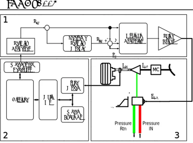
The scheme of Real-Time HILS System, which is shown in Fig 3, is composed of fully realistic hydraulic brake system, real-time interface system and digital controller with Antiskid algorithm. Here, wheels are not rotated because the hydraulic brake system is installed on ground test bench instead of aircraft.
ICCAS2005 June 2-5, KINTEX, Gyeonggi-Do, Korea
Velocity Converter Reference Velocity Module wh V ref V +- e Optimal Controller b T Valve Driver Brake Model Main L/G Wheel Speed Generator Airplane Wheel Dynamics 1 2 3 Pressure IN Pressure Rtn BR P PMC MC CMD I CMD
Fig. 3. Realtime simulation configuration for development of ABS (1: Antiskid Brake Controller, 2: Realtime Dynamics Model, 3: Hydraulic Components(Hardwarfe))
Wheel speed signals, which are fed to the digital control unit are generated by the real-time interface system instead of wheel speed sensors. The real-time interface system is composed of high speed Digital Signal Processors A dynamic model of aircraft with 6-Degree of Freedom is developed by Matlab/Simulink in the Host PC and is downloaded to simulation board. The simulation board simulates the dynamic model at real-time.
During simulation, the real-time interface system generates speed sensor signals of left and right wheel (V1, V2) .The hydraulic brake system is composed of real hydraulic valves, pipes, sensors and brake cylinders. The antiskid controller is tested with the real-time HILS system.
3.2. Aircraft Dynamics Model
The aircraft dynamics model represents force interactions on center of gravity in airframe between nose landing gear, main landing gears, and engine and etc.
At the time of braking on a taxiway, the aircraft is affected by following forces: the aircraft gravitational force, the total aerodynamics force, the engines total thrust force and the landing gear wheels resistance force when moving by the runway surface. The total aerodynamics force is applied at the aircraft center of gravity. The airframe is considered as a rigid beam with mass localized in the center of gravity, it is loaded by the aircraft system of aerodynamic forces and moments (XA, ZA, MA), by aircraft engines thrust (FX, FZ, MZ) and by
responses at the nose (Xng, Zng, Mng) and main (Xmg, Zmg, Mmg)
landing gears. The airframe model represents a vertical motion, a horizontal motion and a rotating motion on center of gravity as well as rotating motions of nose and main landing wheel. The airframe dynamics may be described by the system of 6-order differential equations:
2 1 [ ] 2 ng mg X A pl X X F X m dt x d = + + + (1) Z F Z Z g m dt z d mg ng X A pl − + + + = 1 [ ] 2 2 (2) 22 1 [ A F mg ng] pl M M M M J dt d + + + = θ (3)
x, z – horizontal and vertical coordinates of the airframe center of gravity in the earth coordinate system, m θ – pitch angle, rad
g – free fall acceleration, m/s2
mpl – airframe mass, kg
Jpl – airframe main central moment of inertia relative to the
lateral axis, Nms2
Fig. 2 shows, graphical view of aircraft dynamics model.
Fig. 4. The airframe model 3.3. Wheel-brake dynamics model
The wheel-brake dynamics model that is shown in Fig.4 represents interactions between wheels, brakes, pressure generation system, and the brake control unit.
If the braking pressure control current is fed to the solenoid of pressure control valve, then braking pressure on the wheel is modulated. The pressure on each wheel of main landing gear is converted to digital value and fed to brake-wheel dynamics model. And the braking pressures are converted to the braking moment, which are fed to the wheel dynamics. The braking wheel moments are transferred into the aircraft dynamics model and finally the angular velocities of wheels are fed to the brake control unit.
The friction coefficient model is considered as as the function of
µ
max,s
m, andµ
b. [1]Forces between wheel and tire on runway surface are described by equations [3]:
4. Experimental results 4.1. ABS control algorithms
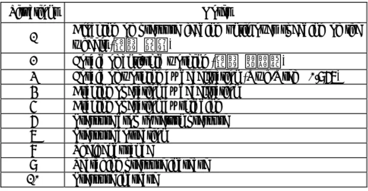
The control algorithm determine presentation of control unit’s output signals depending on incoming signals and commands during operation of the unit in braking mode. Situations (or Events) that are generated by input signals and commands determine value of output signals. The situations for ABS control algorithm are shown in Table 1.
ICCAS2005 June 2-5, KINTEX, Gyeonggi-Do, Korea
Table 1. The situations for antiskid brake control algorithm
Situations Notes 1 Blocking of pressure feeding until over speeding of the
wheels (제동 시작)
2 Forbid of anti-skid working (제동 끝날때)
3 Forbid of working by deceleration (Vwh/Vref > 0.967) 4 Braking operation by deceleration
5 Braking operation by skidding 6 Pressure drop to return pressure
7 Pressure correction
8 Shelf endurance
9 Searching pressure increase
10 Pressure increase
4.1. Simulation Results
The simulations are performed with the realtime simulation system. Simulation results on a wet road (low adhesion road condition) are presented in Fig. 5. Applying the developed antiskid brake controller the antiskid operation was good. In this simulation, it is assumed that mass of 1,906(kg) an aircraft is landed on t=0(sec) and the pilot applied master cylinder its maximum value on t= 1(sec).
0 5 10 15 20 0 200 400 600 800 (p si ) time (s) 0 5 10 15 20 0 50 100 150 200 (r ad /s )
Master Cylinder Pressure Braking Pressure Reference Velocity Wheel Velocity
(a) Velocities and Braking Pressures
0 5 10 15 20 0 5 10 15 0 5 10 15 20 0 10 20 30 40 50 (m A ) time (s) Control Situation Ref. Current Feedback Current (b)Control Situation and Current
Fig. 5. Simulation result on a wet road (µmax=0.2)
5. Conclusions
In this paper, a Mark IV type - fully digital - brake controller is studied and presented. For the development of its control algorithms, a 5-DOF (Degree of Freedom) aircraft landing model is composed in the form of the Matlab/Simulink model at first. Then, braking moment control algorithms using wheel decelerations and slips are made. The developed algorithms are tested in software simulations using state-flow toolboxes in matlab/simulink model. Also, a real-time simulation systems are made, which use hydraulic brake systems of a real aircraft, pressure control valves and its controller as hardware components of HIL (Hardware In-the-Loop) simulation. Algorithms tested in software simulations are coded into the controller and the real-time landing simulations are made in very severe road conditions. The processes and results of both experiments are presented.
References
[1] G.A. Woo, J.W. Jeon, K.C. Lee and Y.J.Kim “Evaluation of the Friction Coefficient from the Dynamometer Test of the Aircraft”, Key Engineering Materials Vols.277-279, pp. 757-764, 2005
[2] J.W. Jeon et all, “Real-Time Test of Aircraft Brake-By-Wire System with HILS & Dynamometer System”, IEEE International Conference on Mechatronics, 2004 [3] G.A. Woo, J.W. Jeon, K.C. Lee and Y.J.Kim, “Evaluation of the Friction Coefficient from the Dynamometer Test of the Aircraft”, International Conference on Control, Automation and Systems, pp. 548-552, Oct. 22-25, 2003.
[4] J.W. Jeon, K.C. Lee, D.H. Hwang, S.H. Lee, J.H. Lee and Y.J.Kim, "The Research of Real-Time Test of Brake-By-Wire System for Aircraft using HILS & Dynamometer System", IEEE, IECON 04, Nov., 2004.
[5] J.W. Jeon, K.C. Lee, D.H. Hwang, J.H. Lee, Y.J.Kim, and S.H. Lee, "The Research of Development of Brake-By-Wire System for Aircraft", International Conference on Electrical Machines and Systems, Nov., 2004